1. Introduction
The DFROBOT C1001 60GHz mmWave Indoor Fall Detection Sensor is designed for precise human presence, fall, and sleep monitoring. Utilizing 60GHz millimeter-wave radar technology, this sensor offers advanced capabilities for detecting human posture, movement, and vital signs without requiring physical contact. It is compatible with development platforms such as Arduino, ESP32, and Micro:bit, making it suitable for various embedded applications.
2. Product Features
- Accurate Fall Detection: Implements human posture recognition through point cloud imaging algorithms to accurately detect falls.
- Precise Life Detection: Offers precise life detection, accurately reporting on fall status, duration of stay, and stationary body status.
- Sleep Monitoring: Perceives human biological presence and movement, continuously recording human presence. Based on changes in body movement and breathing heart rate during sleep, it makes real-time judgments on the target's sleep status and breathing heart rate. After a period of sleep, it outputs a sleep score, which can be incorporated into health monitoring applications.
- 60GHz mmWave Technology: Provides high-resolution detection capabilities for indoor environments.
- Wide Compatibility: Designed for integration with popular microcontrollers like Arduino, ESP32, and Micro:bit.

Figure 2.1: Visual representation of fall detection and sleep monitoring capabilities.
3. Specifications
| Parameter | Value |
|---|---|
| Brand | DFROBOT |
| Model | C1001 |
| Technology | 60GHz mmWave Radar |
| Item Weight | 0.11 Kilograms |
| Maximum Detection Range | 11 Meters |
| Compatible Devices | ESP32, Arduino UNO, Micro:bit |
| Built-In Media | C1001 mmWave Human Detection Sensor x1 |

Figure 3.1: Dimensions of the C1001 sensor module.
4. Setup Guide
4.1 Pinout Description
The C1001 sensor module features several pins for power, ground, and communication. Understanding the pinout is crucial for correct integration with your development board.
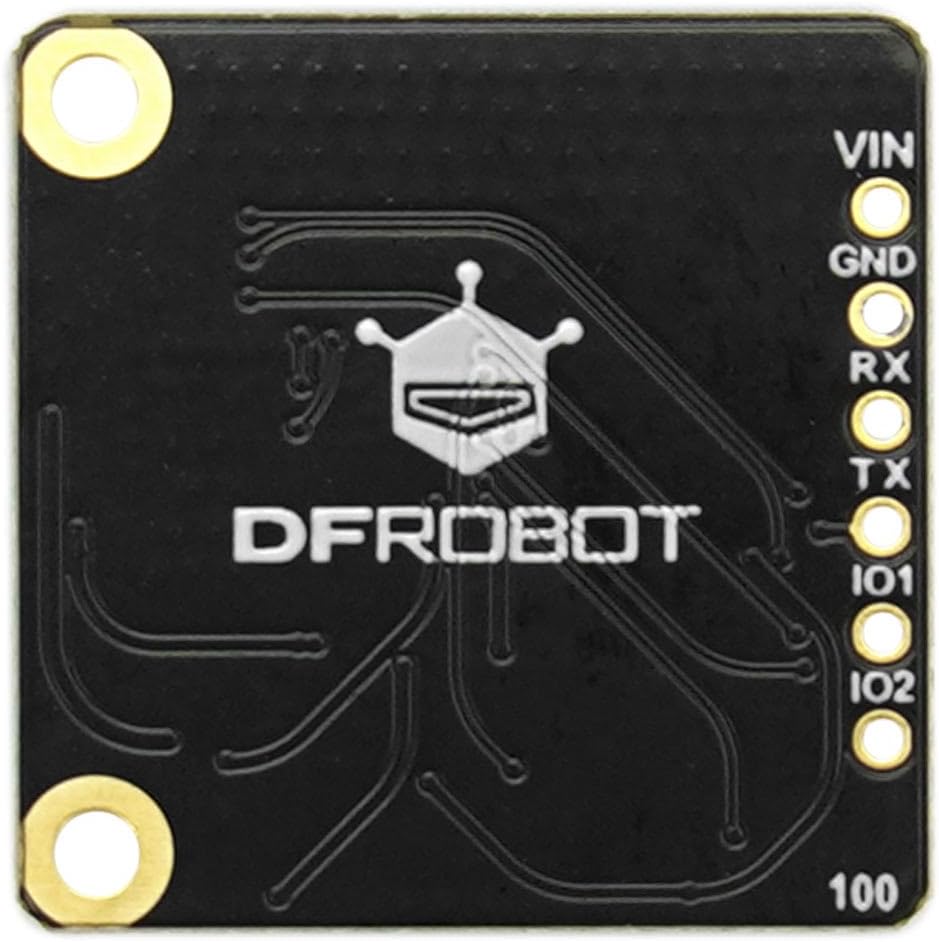
Figure 4.1: C1001 Sensor Pinout.
- VIN: Voltage Input (Power Supply). Connect to the 3.3V or 5V output of your development board.
- GND: Ground. Connect to the ground pin of your development board.
- RX: Receive Data. Connect to the TX pin of your development board for serial communication.
- TX: Transmit Data. Connect to the RX pin of your development board for serial communication.
- IO1, IO2: General Purpose Input/Output pins. These may be used for specific control or status signals depending on the firmware and application.
4.2 Hardware Connection
To connect the C1001 sensor to an Arduino UNO or ESP32 board, follow these general steps:
- Connect the VIN pin of the C1001 sensor to the 5V (for Arduino UNO) or 3.3V (for ESP32) pin on your development board.
- Connect the GND pin of the C1001 sensor to a GND pin on your development board.
- Connect the TX pin of the C1001 sensor to the RX pin (e.g., Digital Pin 0 for Arduino UNO, or a designated RX pin for ESP32) on your development board.
- Connect the RX pin of the C1001 sensor to the TX pin (e.g., Digital Pin 1 for Arduino UNO, or a designated TX pin for ESP32) on your development board.
- Ensure a common ground connection between the sensor and the development board.
Note: Specific pin assignments for RX/TX on ESP32 or Micro:bit may vary. Refer to your development board's documentation for recommended serial communication pins.

Figure 4.2: C1001 sensor with a pin header for connection.
4.3 Software Configuration
To utilize the C1001 sensor, you will need to implement appropriate software on your chosen development platform.
- Libraries: DFROBOT typically provides libraries for their sensors. Search for "DFROBOT C1001 library" for Arduino IDE or PlatformIO.
- Serial Communication: The sensor communicates via UART (serial). Initialize a serial port on your microcontroller at the correct baud rate (refer to the sensor's datasheet for the default baud rate).
- Data Interpretation: The library will handle the parsing of data received from the sensor, providing high-level information such as fall status, presence detection, and sleep parameters.
5. Operating Instructions
5.1 Fall Detection
The C1001 sensor continuously monitors the environment for human presence and posture. When a fall event is detected, the sensor's internal algorithms analyze the point cloud data to confirm the fall. The sensor will then output a signal or data indicating a fall status, along with information on the duration of stay in a fallen or stationary position.
5.2 Sleep Monitoring
For sleep monitoring, the sensor tracks subtle movements and vital signs (breathing heart rate) of a person during sleep. It can differentiate between various sleep states and provide real-time judgments. After a period of monitoring, it can generate a sleep score based on collected parameters, which can be integrated into health monitoring applications.
5.3 Detection Range and Placement
The sensor has a maximum detection range of 11 meters. For optimal performance, consider the placement of the sensor to cover the desired area. The fall detection range and human body stationary/trigger ranges are typically conical, extending from the sensor.

Figure 5.1: C1001 Sensor Detection Range Diagram.
6. Maintenance
- Keep Clean: Ensure the sensor's surface is free from dust, dirt, or obstructions that could interfere with its millimeter-wave signals. Use a soft, dry cloth for cleaning.
- Environmental Conditions: Operate the sensor within its specified environmental conditions (temperature, humidity) to ensure longevity and accurate performance. Avoid extreme temperatures or high humidity.
- Physical Protection: Protect the sensor from physical impact or excessive vibration. If integrating into a product, ensure it is housed in a suitable enclosure.
- Firmware Updates: Periodically check the DFROBOT official website or product page for any available firmware updates that may improve performance or add new features.
7. Troubleshooting
- No Data Output:
- Check all power and ground connections (VIN, GND).
- Verify RX/TX connections are correctly wired (TX to RX, RX to TX).
- Ensure the serial port on your microcontroller is initialized at the correct baud rate.
- Confirm the sensor is receiving adequate power.
- Inaccurate Detection:
- Ensure the sensor's field of view is clear of obstructions.
- Verify the sensor is placed at an optimal height and angle for the intended detection area.
- Check for strong interference sources (e.g., other 60GHz devices, large metallic objects) in the vicinity.
- Review the sensor's configuration parameters in your code (if adjustable).
- Sensor Not Responding:
- Power cycle the sensor and development board.
- Re-upload your microcontroller code to ensure it's running correctly.
- If possible, try connecting the sensor to a different development board or using a known-good example sketch.
8. Warranty and Support
For warranty information, technical support, and additional resources, please refer to the official DFROBOT website. DFROBOT provides comprehensive documentation, forums, and customer service to assist with product integration and troubleshooting.
Official Website: www.dfrobot.com