1. Product Overview
The Brilluxa 9600D-1T-00150D is a Variable Frequency Drive (VFD) specifically designed for solar photovoltaic pump motor control applications. This inverter efficiently converts DC power from solar panels into AC power to drive 3-phase motors, such as those used in water pumps. It features a robust design with an ABS and aluminum construction, ensuring durability and reliable performance in various environments.
Key features include a clear digital display for easy operation, a double-layer board design for enhanced reliability, and an efficient cooling system to prevent overheating.

Figure 1: Front view of the Brilluxa 9600D-1T-00150D Solar VFD Inverter, showing the digital display, control buttons, and cooling fins.
2. Technical Specifications
| Parameter | Value |
|---|---|
| Item Type | Variable Frequency Drive |
| Material | ABS + Aluminum |
| Model | 9600D-1T-00150D |
| Input Voltage | DC200-400V |
| Output Voltage | AC 3PH 0-220V |
| Output Frequency | 0-650Hz |
| Rated Power | 1.5KW |
| Rated Current | 7A |
| Dimensions (L x W x H) | Approx. 82 x 145 x 155mm / 3.23 x 5.71 x 6.1in |
| Item Weight | Approx. 2.49 pounds |

Figure 2: Dimensional view of the inverter, showing its length, width, and height measurements.
3. Safety Information
Please read this manual thoroughly before installation, operation, or maintenance of the device. Failure to follow safety instructions may result in personal injury or equipment damage.
- Electrical Hazard: Ensure all power sources are disconnected before opening the cover or performing any maintenance. Only qualified personnel should perform electrical connections.
- Voltage Compatibility: Always ensure the input and output voltages match the specifications of your system.
- Simultaneous Input: Do not connect both AC input and DC input switches simultaneously, as this will damage the inverter or solar panel.
- Overload Protection: Avoid operating the inverter with an overload. The inverter's power must be sufficient for the motor. Running a motor at frequencies significantly above 50Hz with an undersized inverter can lead to frequent overload protection faults, damage to the inverter, or motor burnout.
- Environmental Conditions: Install the inverter in a well-ventilated area, away from direct sunlight, moisture, and corrosive substances.
- Cooling: Ensure proper airflow around the unit for effective heat dissipation. The inverter is equipped with a DC 24V cooling fan and an external aluminum cooling base.
4. Installation and Setup
4.1 Unpacking and Inspection
Upon receiving the package, carefully unpack the inverter and inspect it for any signs of physical damage. Ensure all components listed in the package contents are present.
4.2 Mounting
Mount the inverter vertically on a stable, non-flammable surface. Allow sufficient clearance around the unit for proper ventilation and heat dissipation.
4.3 Electrical Connections
Refer to the wiring diagram below for correct electrical connections. All wiring should be performed by a qualified electrician in accordance with local electrical codes.

Figure 3: Detailed wiring diagram showing connections for AC grid, solar panel, protection diode, and water pump motor to the inverter terminals.
- DC Input (Solar Panels): Connect the solar panels to the P+ and N- terminals. For a 220V motor, the total series voltage of solar panels must be between 200V-400V. For a 380V motor, the total series voltage should be 400V-700V. The total power of parallel-connected solar panel groups should be at least 1.2 times the inverter's power.
- AC Output (Motor): Connect the 3-phase motor to the U, V, W terminals.
- AC Input (Optional): If using an AC grid input, connect it to the R, S, T terminals. Important: When the main circuit AC power is connected, ensure the Q2 switch (disconnecting solar input) is open to prevent damage to the inverter.
- Protection Diode: Install a protection diode as shown in the diagram for solar panel input.

Figure 4: Illustrative diagram of a typical photovoltaic water pump system, showing solar modules, water tower, water purification device, and the inverter connected to a well pump.
5. Operation
5.1 Control Panel Overview
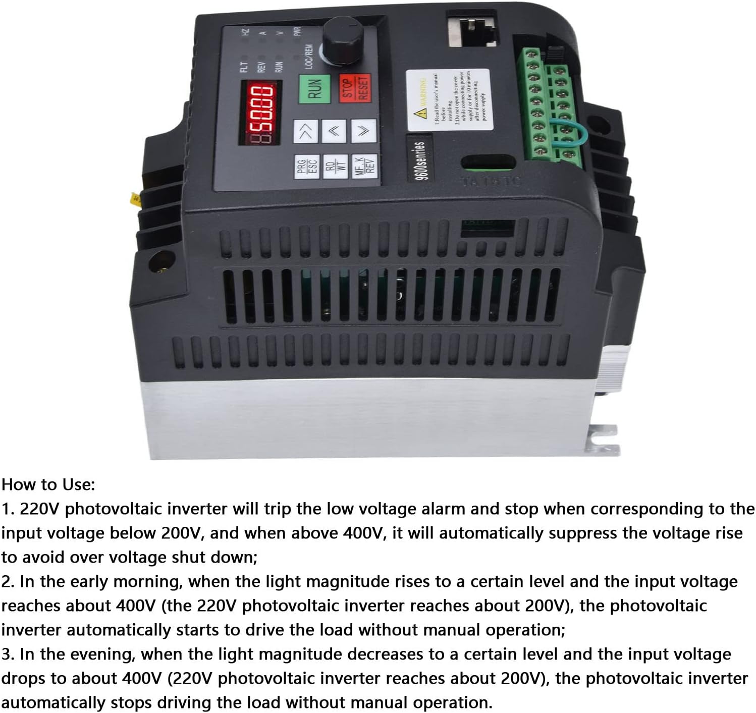
Figure 5: Top view of the inverter showing the digital display, control buttons (PRG/ESC, RD/WT, MF.K/REV, RUN, STOP/RESET), and the rotary knob for frequency adjustment.
The inverter features a red digital tube display for clear visibility and intuitive control buttons for manual operation. The rotary knob allows for precise frequency adjustment.
5.2 Basic Operation Sequence
- Power On: After ensuring all connections are secure and correct, apply DC power from the solar panels.
- Automatic Start: The inverter is designed to automatically start driving the load (e.g., pump) when the input voltage from the solar panels reaches an adequate level (e.g., above 200V for a 220V system).
- Low Light Conditions:
- In the early morning, as light intensity increases and the input voltage rises (e.g., to about 200V for a 220V inverter), the inverter will automatically begin operation.
- In the evening, as light intensity decreases and the input voltage drops (e.g., to about 200V for a 220V inverter), the inverter will automatically cease operation.
- Frequency Adjustment: Use the rotary knob to adjust the output frequency, thereby controlling the motor speed.
- Stop/Reset: Press the STOP/RESET button to halt operation or clear fault indications.
5.3 Features Overview

Figure 6: Image highlighting the efficient cooling system and the robust double-layer board design of the inverter.

Figure 7: Image illustrating the user-friendly control interface and the security-focused design of the inverter.
6. Maintenance
Regular maintenance ensures optimal performance and extends the lifespan of your inverter.
- Cleaning: Periodically clean the exterior of the inverter with a soft, dry cloth. Ensure ventilation openings are free from dust and debris. Do not use liquid cleaners.
- Fan Inspection: Check the cooling fan for proper operation and ensure it is free from obstructions.
- Connection Check: Periodically inspect all electrical connections for tightness and signs of corrosion.
- Environmental Check: Ensure the operating environment remains within specified temperature and humidity ranges.
7. Troubleshooting
This section provides solutions to common issues you might encounter with your inverter.
| Problem | Possible Cause | Solution |
|---|---|---|
| Inverter trips with low voltage alarm | Input DC voltage is below 200V (for 220V output systems) or above 400V. | Verify solar panel connections and output voltage. Ensure the total series voltage of solar panels is within the specified range (DC200-400V). |
| Frequent overload protection fault or inverter damage | Inverter power is less than motor power, or motor is running at excessively high frequencies (e.g., >50Hz) with an undersized inverter. | Ensure the inverter's rated power is greater than or equal to the motor's power. For submersible pumps exceeding 30 meters depth, consider an inverter one or two stages larger and add a reactor between the inverter and pump. Adjust motor operating frequency to avoid overload. |
| Inverter or solar panel damage | AC input and DC input switches are closed simultaneously. | Never close AC input and DC input switches at the same time. Ensure only one power source is active at any given time. |
| Reduced solar energy conversion rate | DC input voltage is not within the recommended range (DC200-400V). | Adjust solar panel configuration (series/parallel) to achieve the recommended DC input voltage for optimal efficiency. |
8. Warranty and Support
Brilluxa products are manufactured to high-quality standards. For specific warranty details, please refer to the documentation included with your purchase or contact Brilluxa customer support.
8.1 Customer Support
If you encounter any issues not covered in this manual or require further assistance, please contact Brilluxa customer support through the retailer where you purchased the product or visit the official Brilluxa store on Amazon: Brilluxa Amazon Store.