1. Introduction
This manual provides essential information for the safe and efficient operation of your PACUM NPS3010W DC Power Supply. The NPS3010W is a miniature switching DC power supply designed for laboratory and DIY applications, offering adjustable output voltage and current. It features a high-precision three-window digital display for voltage, current, and power, ensuring clear monitoring of operational parameters.
Key features include:
- Complete operating protection functions: over temperature, overload, and short circuit protection.
- Compact size, low ripple, lightweight, and high power density for efficiency.
- Voltage stabilization and current limiting capabilities.
- Automatic switching between constant voltage (CV) and constant current (CC) modes.
- Three LED displays for voltage, current, and power with high precision.

Figure 1: Front view of the PACUM NPS3010W DC Power Supply. This image shows the compact design with digital displays for voltage, current, and power, along with control knobs and output terminals.
2. Safety Instructions
Please read and understand all safety instructions before operating the device. Failure to follow these instructions may result in electric shock, fire, or personal injury.
- Always connect the power supply to a grounded outlet.
- Do not operate the device in wet or damp conditions.
- Ensure proper ventilation to prevent overheating. Do not block ventilation openings.
- Do not open the casing of the power supply. There are no user-serviceable parts inside.
- Disconnect power before making any connections or disconnections to the output terminals.
- Use appropriate test leads and ensure they are in good condition.
- Avoid touching live terminals or circuits.
- If the device is damaged, do not use it. Contact qualified service personnel.
3. Product Overview
3.1 Front Panel Controls and Displays

Figure 2: Detailed view of the front panel, showing controls and displays.
- Voltage Display: Shows the output voltage in Volts (V).
- Current Display: Shows the output current in Amperes (A).
- Power Display: Shows the output power in Watts (W).
- V-COARSE / V-FINE: Coarse and fine adjustment knobs for output voltage.
- A-COARSE / A-FINE: Coarse and fine adjustment knobs for output current.
- C.V / C.C Indicators: LEDs indicating Constant Voltage (C.V) or Constant Current (C.C) operating mode.
- ON/OFF Switch: Main power switch for the unit.
- Output Terminals: Positive (+) (red) and Negative (-) (black) terminals for connecting the load.
3.2 Rear Panel Features

Figure 3: Rear panel showing the cooling fan, AC input socket, fuse holder, and voltage switch.
- Cooling Fan: Automatically activates to dissipate heat and maintain optimal operating temperature.
- AC Input Socket: For connecting the main power cord.
- Fuse Holder: Contains the protective fuse.
- AC Input Voltage Switch (115V/230V): Allows selection of the appropriate input voltage for your region. Ensure this is set correctly before connecting to power.
4. Setup
Follow these steps to set up your PACUM NPS3010W DC Power Supply:
- Unpacking: Carefully remove the power supply and all accessories from the packaging. Verify that all components are present: the power supply unit, power cord, and test leads.
- Placement: Place the power supply on a stable, level surface with adequate ventilation. Ensure that the cooling fan and ventilation openings are not obstructed.
- Input Voltage Selection: Locate the AC Input Voltage Switch on the rear panel (Figure 3). Set it to match your local mains voltage (115V or 230V). Incorrect setting can damage the unit.
- Power Connection: Ensure the power supply's ON/OFF switch is in the OFF position. Connect the provided AC power cord to the AC Input Socket on the rear panel, then plug the other end into a grounded wall outlet.
- Output Lead Connection: Connect the test leads to the output terminals. The red lead connects to the positive (+) terminal, and the black lead connects to the negative (-) terminal. Ensure connections are secure.

Figure 4: Typical package contents including the power supply, operation manual, and test leads.
5. Operating Instructions
The PACUM NPS3010W operates in two main modes: Constant Voltage (CV) and Constant Current (CC). The unit automatically switches between these modes depending on the load and set parameters.
5.1 Setting Voltage and Current Limits (Pre-setting)
It is recommended to set the voltage and current limits before connecting the load to prevent damage.
- Ensure the power supply is OFF and no load is connected to the output terminals.
- Turn the power supply ON using the front panel switch.
- Set Voltage: Adjust the V-COARSE knob to set the approximate desired voltage. Then, use the V-FINE knob for precise adjustment. The Voltage Display will show the set value.
- Set Current Limit: Turn the A-COARSE knob fully counter-clockwise (to minimum current). Then, slowly turn the A-FINE knob clockwise to set the desired maximum current limit. The Current Display will show a very low value or zero if no load is connected.
- Once voltage and current limits are set, turn the power supply OFF.
5.2 Connecting Load and Operation
- With the power supply OFF, connect your load to the output terminals, ensuring correct polarity (positive to positive, negative to negative).
- Turn the power supply ON. The voltage and current displays will show the actual output values.
- Constant Voltage (CV) Mode: If the load resistance is high enough, the output voltage will be maintained at the set value, and the C.V indicator will light up. The current supplied will depend on the load.
- Constant Current (CC) Mode: If the load resistance is low, causing the current to exceed the set current limit, the power supply will automatically switch to Constant Current mode. The C.C indicator will light up, and the output current will be maintained at the set limit. The output voltage will drop to protect the load.
- You can adjust voltage and current during operation using the respective coarse and fine adjustment knobs.
- When finished, turn the power supply OFF before disconnecting the load.
6. Maintenance
Proper maintenance ensures the longevity and reliable operation of your power supply.
- Cleaning: Disconnect the power supply from the mains before cleaning. Use a soft, dry cloth to wipe the exterior. Do not use abrasive cleaners or solvents.
- Ventilation: Regularly check that the ventilation openings and cooling fan are free from dust and debris. Use compressed air to gently clear any blockages if necessary.
- Storage: When not in use for extended periods, store the power supply in a cool, dry place, away from direct sunlight and extreme temperatures.
- Fuse Replacement: If the power supply does not turn on, the fuse may need replacement. Disconnect the power cord, open the fuse holder on the rear panel, and replace the fuse with one of the same type and rating (e.g., T2A 250V).
7. Troubleshooting
If you encounter issues with your power supply, refer to the following common problems and solutions:
| Problem | Possible Cause | Solution |
|---|---|---|
| No power/Unit does not turn on. | Power cord not connected; AC input voltage switch incorrect; Blown fuse. | Check power cord connection; Verify AC input voltage switch setting; Replace fuse with correct type and rating. |
| No output voltage/current. | Output terminals not connected; Output voltage/current set to zero; Overload/short circuit protection active. | Ensure load is properly connected; Adjust V/A knobs; Check load for short circuits or excessive current draw. |
| Unit overheats. | Blocked ventilation; Excessive load. | Ensure ventilation openings are clear; Reduce load or operate within specified limits. |
| Voltage/Current display inaccurate. | Calibration required (unlikely for new unit); External interference. | If persistent, contact customer support. |
If the problem persists after attempting these solutions, please contact customer support.
8. Specifications
The following are the technical specifications for the PACUM NPS3010W DC Power Supply:
- Model: NPS3010W (3 Digits 30V 10A variant)
- Input Voltage: AC 115V/230V ±10% (switchable)
- Output Voltage: 0-30V DC (Adjustable)
- Output Current: 0-10A DC (Adjustable)
- Display: 3-digit LED for Voltage, Current, and Power
- Voltage Display Accuracy: 0.1V
- Current Display Accuracy: 0.01A
- Operating Modes: Constant Voltage (CV), Constant Current (CC)
- Protection: Over Temperature Protection (OTP), Overload Protection (OLP), Short Circuit Protection (SCP)
- Ripple & Noise: Low
- Weight: Approximately 3000 Grams (3 kg)
- Dimensions: Refer to Figure 5 for approximate dimensions.
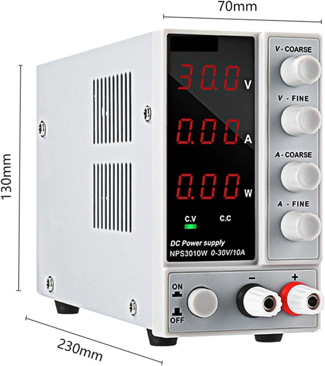
Figure 5: Approximate dimensions of the PACUM NPS3010W unit (230mm depth, 70mm width, 130mm height).
9. Warranty and Support
PACUM products are designed for reliability and performance. For warranty information, please refer to the documentation included with your purchase or contact your retailer. If you require technical assistance or have questions regarding the operation of your NPS3010W DC Power Supply, please contact PACUM customer support through the vendor you purchased the product from.
For further assistance, you may visit the PACUM brand page on Amazon: PACUM Brand Store