1. Introduction
This manual provides detailed instructions for the installation, operation, and management of your Goalake 5 Port Gigabit Easy Smart Managed Ethernet Switch. Please read this manual thoroughly before using the device to ensure proper setup and optimal performance. This switch is designed to expand your network connectivity with high-speed Gigabit Ethernet ports and offers smart management features for enhanced control.
2. Product Overview
2.1 Key Features
- 5 Gigabit Ethernet Ports: Provides high-speed network connectivity for multiple devices.
- Easy Smart Management: Configurable via a dedicated mobile application or a web-based interface.
- Advanced Network Control: Includes features such as VLAN support, QoS optimization, static MAC addressing, storm control, and port mirroring.
- PoE Powered (PoE IN): Port 5 can receive power from an upstream PoE switch, eliminating the need for a separate power adapter in certain scenarios.
- Robust Design: Features a fanless metal casing for efficient heat dissipation, quiet operation, and durability.
- Flexible Installation: Supports both desktop placement and wall mounting.
2.2 Package Contents
- 1 x Goalake 5 Port Gigabit Ethernet Switch
- 1 x Power Cord
- 1 x User Manual (this document)
2.3 Physical Appearance and Ports
The Goalake 5 Port Gigabit Easy Smart Managed Ethernet Switch features a compact metal design with five Gigabit Ethernet ports and a power indicator.

Image 1: Front view of the Goalake 5 Port Gigabit Easy Smart Managed Ethernet Switch, showing five RJ45 Gigabit ports (1-4 for data, 5 for PoE IN/data) and a PWR indicator light.

Image 2: An illustration demonstrating the Goalake 5 Port Easy Smart Managed Switch expanding a network by connecting devices such as a Desktop PC, Printer, Laptop, IP Camera, Access Point, IP Phone, and NVR.

Image 3: A diagram illustrating the compact dimensions (4 inches length, 2.4 inches width, 0.96 inches height) and key features of the switch, including metal casing, fanless design, noiseless operation, compact desktop design, and wall-mounting capability.
3. Setup
3.1 Powering the Switch
The switch can be powered in two ways:
- Using the Included Power Adapter: Connect the provided power cord to the switch's DC input port and then to a standard electrical outlet.
- Using PoE IN (Port 5): If you have an upstream PoE switch, connect an Ethernet cable from a PoE-enabled port on that switch to Port 5 (PoE IN) on your Goalake switch. This allows the switch to receive power directly over the Ethernet cable, eliminating the need for a separate power adapter.

Image 4: An illustration demonstrating the PoE-IN design. The Goalake Cloud Managed Switch can be powered by connecting Port 5 (PoE IN) to an upstream PoE Switch or a PoE power supply, using a single Ethernet cable for both data and power.
3.2 Connecting Network Devices
Once the switch is powered on, connect your network devices (e.g., computers, IP cameras, IP phones, access points) to any of the Gigabit Ethernet ports (Ports 1-5) using standard Ethernet cables. The switch supports auto MDI/MDI-X, so you do not need to worry about cable types (straight-through or crossover).

Image 5: A visual representation of the switch's plug-and-play functionality, showing a computer, IP camera, and IP phone connected to the Gigabit ports. Icons indicate features like MDI/MDIX, 5x1Gb Ethernet ports, 10Gbps switching capacity, advanced smart web/APP management, port restart, and scheduled restart.
3.3 Initial Power-On
After connecting power and devices, the PWR indicator light on the switch should illuminate, indicating that the device is operational. The switch is designed for plug-and-play operation for basic network expansion.
4. Operating Instructions
4.1 Easy Smart Management (APP/Web Interface)
The Goalake switch offers flexible management options via a mobile application or a web-based interface. This allows for remote and local control of advanced features.
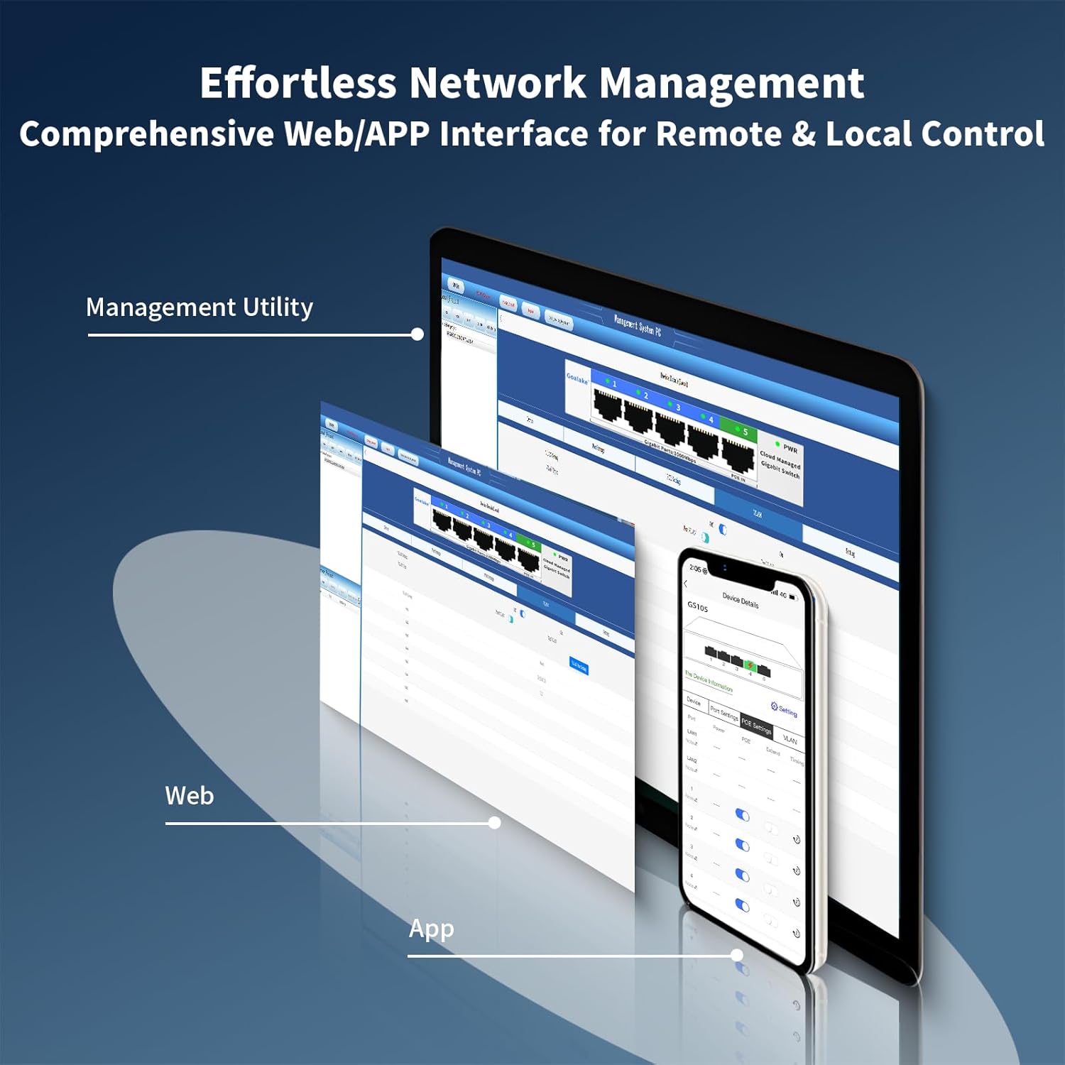
Image 6: Screenshots depicting the comprehensive web interface and mobile application (APP) for effortless network management of the Goalake switch, providing remote and local control.
To access the management interface:
- Mobile App: Download the official Goalake management app from the Google Play Store (for Android) or Apple App Store (for iOS). Follow the in-app instructions to discover and manage your switch.
- Web Interface: Connect a computer to the switch. Open a web browser and enter the switch's default IP address (refer to the product documentation or use a network scanner to find it if changed). Log in with the default credentials (usually provided in the quick start guide or on the device label).
4.2 Intelligent Cloud Detection
The switch features intelligent cloud detection for online monitoring of each device's status. By observing the port color indicators, you can quickly assess network performance and data transmission status for each switch port.

Image 7: An illustration of intelligent cloud detection, showing how port color indicators (Powered, Good, Normal, Poor, Disconnected) provide real-time feedback on network performance and data transmission. A mobile app screenshot displays detailed device information and port settings.
Port Icon Description:
- Powered: Indicates the port is active and receiving power.
- Good: Optimal network performance.
- Normal: Acceptable performance.
- Poor: Suboptimal performance. If yellow or orange, consider checking the network cable quality or enabling Extended Mode if the cable length exceeds 100m.
- Disconnected: No active connection detected.
5. Advanced Features
5.1 VLAN (Virtual Local Area Network)
VLANs allow you to segment your network into logical groups, improving traffic management, security, and network efficiency. You can create separate VLANs for different departments or types of traffic (e.g., surveillance, office, guest network).

Image 8: A diagram demonstrating VLAN functionality, segmenting a network into VLAN1 (Surveillance), VLAN2 (Office Network), and VLAN3 (Guest Network) using the Goalake switch. This allows for better traffic management and security.
Configuration of VLANs is performed through the web or app management interface. Refer to the software's help section for detailed steps on creating and assigning VLANs to specific ports.
5.2 QoS (Quality of Service)
QoS allows you to prioritize network traffic, ensuring that critical applications (e.g., video conferencing, VoIP) receive sufficient bandwidth and experience minimal latency. This helps in maintaining a lag-free experience for important services.

Image 9: An image emphasizing QoS capabilities for a lag-free experience, showing a business meeting with video conferencing, indicating that the switch can prioritize traffic for optimal performance.
QoS settings can be configured via the management interface to define priority levels for different types of traffic or specific devices.
5.3 Other Advanced Features
- Static MAC Addressing: Manually assign MAC addresses to ports for enhanced security and control.
- Storm Control: Prevents network performance degradation caused by excessive broadcast, multicast, or unknown unicast traffic.
- Port Mirroring: Copies traffic from one port to another for network monitoring and analysis.
- IEEE802.3X Full-Duplex Flow Control: Manages data flow to prevent packet loss in full-duplex connections.
- Backpressure Half-Duplex Flow Control: Manages data flow in half-duplex connections.
6. Installation
The Goalake 5 Port Gigabit Easy Smart Managed Ethernet Switch offers versatile installation options:
- Desktop Placement: Simply place the switch on a flat, stable surface. Ensure adequate ventilation around the device.
- Wall Mounting: The switch is designed for easy wall mounting. Use appropriate screws and anchors (not included) to secure the device to a wall. Refer to the mounting holes on the underside of the switch for proper alignment.
7. Troubleshooting
If you encounter issues with your Goalake switch, consider the following troubleshooting steps:
- No Power: Ensure the power cord is securely connected to both the switch and a working power outlet. If using PoE IN, verify the upstream PoE switch is providing power and the Ethernet cable is functional.
- No Network Connectivity: Check all Ethernet cable connections. Ensure cables are securely plugged into both the switch and the connected devices. Verify that the PWR indicator is on. Check the port status indicators (refer to Section 4.2) for any 'Disconnected' or 'Poor' status.
- Slow Network Speed: Check the port status indicators for 'Poor' status. This might indicate a faulty or low-quality Ethernet cable, especially for longer runs. Ensure all connected devices are capable of Gigabit speeds.
- Cannot Access Management Interface: Verify your computer is on the same network segment as the switch. Ensure you are using the correct IP address and login credentials. Try restarting the switch and your computer.
- Unusual Network Activity: If you observe unexpected network behavior, review your switch's configuration via the management interface. Ensure no unauthorized settings have been applied. If concerns persist, consider resetting the switch to factory defaults (refer to the management interface documentation for this procedure).
8. Specifications
| Feature | Specification |
|---|---|
| Brand | Goalake |
| Model Number | 5 Gigabit Ports |
| Number of Ports | 5 |
| Data Transfer Rate | 1000 Gigabits Per Second (per port) |
| Interface Type | PoE, RJ45 |
| Case Material | Metal |
| Item Weight | 5.3 ounces (150 Grams) |
| Voltage | 57 Volts (PoE IN) |
| Upper Temperature Rating | 60 Degrees Celsius |
| Package Dimensions | 4.33 x 2.83 x 2.52 inches |
| Color | Black |
| Compatible Devices | Desktop, Laptop, Printer, Gaming console, Camera, Router |
9. Warranty and Support
Goalake provides a comprehensive one-year after-sales service plan for this product. Should any issues arise within the first year from your order date, we offer replacements to ensure your satisfaction. For support or warranty claims, please contact Goalake customer service through the official channels provided at the time of purchase.