
1. Introduction
The Swagell Fosc21C1 is a compact, 2-channel USB PC oscilloscope designed for various measurement and development applications. It offers a 1MHz sampling rate and integrates seamlessly with a computer for data acquisition, analysis, and storage. This manual provides essential information for setting up, operating, and maintaining your Fosc21C1 oscilloscope.
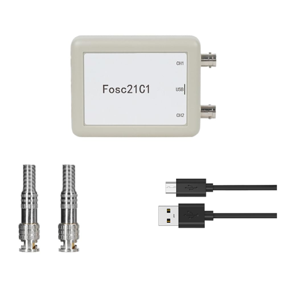
Figure 1: Swagell Fosc21C1 USB PC Oscilloscope
2. Product Overview and Features
The Fosc21C1 oscilloscope provides robust functionality for signal analysis and data logging. Key features include:
- 2-Channel Input: Simultaneous display and measurement of two independent signals.
- 1MHz Sampling Rate: Capable of capturing signals up to 250kHz.
- Automatic Amplitude Measurement: Simplifies signal analysis.
- Trigger Functionality: Adjustable trigger level with rising or falling edge options for precise signal capture. Any channel can be set as the trigger source.
- Data Logging and Storage: Records and stores waveforms for up to 90 hours, with a storage depth of 8,388,608 x 5 data points.
- PC Integration: Connects via Micro-USB 2.0, allowing data to be saved, backed up, and analyzed on a computer using dedicated software.
- Differential Signal Display: Ability to display differential signals from the two channels.
- Long-Term Monitoring: Ideal for archiving and monitoring electrical equipment operation, as well as collecting environmental data like temperature, humidity, and light over extended periods.

Figure 2: Fosc21C1 Oscilloscope highlighting 1MHz sampling rate, ±80V measurement voltage, and 2-channel capability, along with included BNC connectors and USB cables.
3. Package Contents
Verify that all items are present in your package:
- 1 x Fosc21C1 Oscilloscope Unit
- 2 x BNC Connectors
- 1 x USB Data Cable
4. Specifications
| Parameter | Value |
|---|---|
| Interface Type | Micro-USB 2.0 |
| Signal Input Interface | BNC interface (for oscilloscope probe line) |
| Maximum Sampling Rate | 1MHz (2 x 1MHz) |
| Operating Voltage | 5V (via Micro-USB interface) |
| Current Consumption | Below 2A |
| Measurable Frequency Range | 0Hz ~ 250kHz |
| Amplitude Adjustment Range | 2mV, 5mV, 10mV, 20mV, 25mV, 40mV, 50mV, 80mV, 0.1V, 0.2V, 0.5V, 1V, 2V, 5V, 10V |
| Input Impedance | 1 MΩ/20pF |
| Maximum Measurable Voltage | ±80 V |
| Time Domain Range | 10 µS to 10800 S |
| Data Recording/Storage Depth | 8,388,608 x 5 |
| Maximum Recording/Storage Time | 90 hours |
| Host Size | 115mm x 70mm x 29mm |
| Material | Plastic |
| Weight | 106 g |
5. Setup
Follow these steps to set up your Fosc21C1 oscilloscope:
- Install Software: Before connecting the device, install the dedicated PC software on your computer. Refer to the software's installation guide for detailed instructions.
- Connect USB Cable: Use the provided USB data cable to connect the Fosc21C1 oscilloscope to an available USB port on your computer. The Micro-USB port on the oscilloscope is located on the side.
- Connect Probes: Attach your oscilloscope probes to the BNC input interfaces (CH1 and CH2) on the Fosc21C1 unit. Ensure a secure connection.
- Power On: The device will draw power directly from the USB connection. Once connected, launch the installed PC software. The software should automatically detect the oscilloscope.

Figure 3: Connecting the Fosc21C1 oscilloscope to a computer via USB.

Figure 4: Close-up of the Fosc21C1's Micro-USB power/data port and BNC input channels (CH1 and CH2).
6. Operating Instructions
Operating the Fosc21C1 primarily involves using the dedicated PC software. Refer to the software's user guide for comprehensive details on all functions. Below are general operational guidelines:
- Launch Software: After connecting the oscilloscope, open the Fosc21C1 PC software. The software will automatically transfer any previously saved data upon startup.
- Configure Channels: In the software interface, select and configure the desired input channels (CH1, CH2). You can adjust amplitude ranges (e.g., 2mV to 10V) and other channel-specific settings.
- Set Trigger: Utilize the trigger function to stabilize waveforms. You can set any channel as the trigger source and specify rising or falling edge triggers. Adjust the trigger level to capture specific signal events.
- View Waveforms: The software will display the captured waveforms in real-time. You can zoom, pan, and analyze the waveforms using the software's tools. The software supports synchronous display of both channels.
- Data Recording: To record data for long-term analysis, activate the data logging feature within the software. The Fosc21C1 can record data for up to 90 hours.
- Data Management: Saved data can be backed up and reloaded later for review. The software allows for displaying waveforms from backed-up data.
- Differential Measurement: The software supports displaying differential signals between the two channels, useful for specific measurement scenarios.

Figure 5: Fosc21C1 oscilloscope in use, measuring signals on a circuit board.
7. Maintenance
Proper maintenance ensures the longevity and accuracy of your Fosc21C1 oscilloscope:
- Cleaning: Use a soft, dry cloth to clean the exterior of the device. Do not use abrasive cleaners or solvents, as they may damage the plastic housing.
- Storage: Store the oscilloscope in a cool, dry place away from direct sunlight, extreme temperatures, and high humidity.
- Handling: Handle the device with care to avoid physical damage. Do not drop or expose it to excessive vibration.
- Cable Care: Ensure USB and BNC cables are not bent sharply or subjected to undue stress, which can damage internal wiring.
8. Troubleshooting
If you encounter issues with your Fosc21C1 oscilloscope, refer to the following common troubleshooting steps:
- Device Not Detected:
- Ensure the USB cable is securely connected to both the oscilloscope and the computer.
- Try connecting to a different USB port on your computer.
- Verify that the necessary drivers and PC software are correctly installed.
- Restart your computer and the oscilloscope software.
- No Waveform Display:
- Check that the probes are correctly connected to the BNC inputs and to the circuit under test.
- Ensure the input signal is within the measurable voltage and frequency range of the oscilloscope.
- Adjust the amplitude and time base settings in the software.
- Check trigger settings; an improperly set trigger can prevent waveform display.
- Inaccurate Readings:
- Ensure probes are properly calibrated (if applicable to your probes).
- Check for external interference or noise in the measurement environment.
- Verify that the software settings (e.g., input coupling, probe attenuation) match your setup.
9. Warranty and Support
For warranty information and technical support, please refer to the documentation provided with your purchase or contact Swagell customer service through their official website or your retailer. Keep your purchase receipt as proof of purchase.