1. Introduction
This manual provides detailed instructions for the installation, operation, and maintenance of your Balam Rush Tank Master 9600 TB (CS-985) Mid-Tower Gaming PC Case. Designed for optimal performance and aesthetics, this case features a dual-chamber layout, tempered glass panels, and integrated ARGB lighting to enhance your computing experience. Please read this manual thoroughly before beginning installation to ensure proper setup and safe operation.

Image 1.1: Front-left view of the Balam Rush Tank Master 9600 TB PC Case, showcasing its tempered glass panels and pre-installed ARGB fans.
2. Safety Information
- Always disconnect the power supply from the wall outlet before installing or servicing any components inside the PC case.
- Be aware of sharp edges inside the case. Handle components carefully to avoid injury.
- Tempered glass panels are fragile. Handle them with care and place them on a soft, flat surface when removed.
- Wear an anti-static wrist strap or frequently touch a grounded metal object to prevent electrostatic discharge (ESD) damage to sensitive electronic components.
- Keep the case and its components away from liquids and excessive humidity.
3. Package Contents
Verify that all items are present in the package:
- Balam Rush Tank Master 9600 TB PC Case
- Accessory Box (containing screws, cable ties, and this user manual)
- Pre-installed ARGB Fans (4 units)
4. Product Features
- Dual Chamber Design: Separates power supply and storage from main components for improved airflow and cable management.
- Tempered Glass Panels: Provides a clear view of your internal components and ARGB lighting.
- Pre-installed ARGB Fans: Four addressable RGB fans are included for immediate cooling and aesthetic enhancement.
- Extensive Cooling Support: Accommodates multiple fans and liquid cooling radiators for superior thermal performance.
- Motherboard Compatibility: Supports ATX, Micro-ATX, and Mini-ITX motherboard form factors.
- Flexible Storage Options: Features dedicated mounts for 2x 2.5" SSDs and 2x 3.5" HDDs.
- Modern Front I/O Ports: Includes USB Type-C, USB 3.0, USB 2.0, HD Audio, and an RGB control button for convenient connectivity.
- Generous GPU Clearance: Supports graphics cards up to 410mm in length.
- Optimized Cable Management: Offers 90mm of depth in the secondary chamber for clean cable routing.

Image 4.1: Illustration of the dual chamber design, separating components for better airflow and cable management.
5. Specifications
| Feature | Specification |
|---|---|
| Model | TANK MASTER 9600 TB (CS-985) |
| Case Type | Mid-Tower |
| Motherboard Support | ATX, Micro-ATX, Mini-ITX |
| Max GPU Length | 410 mm |
| Max CPU Cooler Height | 163 mm |
| Drive Bays | 2x 2.5" SSD, 2x 3.5" HDD |
| Front I/O Ports | 1x USB Type-C, 1x USB 3.0, 1x USB 2.0, HD Audio (Mic/Headphone), RGB Control Button, Power Button |
| Dimensions (L x W x H) | Approximately 426 x 230 x 398 mm (Case body) |
| Material | Steel, Tempered Glass |
| Weight | 7.3 kg |
| Cooling Method | Air (4x ARGB fans pre-installed) |

Image 5.1: Case dimensions and maximum clearances for GPU and CPU cooler.
6. Setup Guide
6.1. Preparing the Case
- Carefully remove the case from its packaging.
- Place the case on a stable, flat surface.
- Remove the tempered glass side panels by unscrewing the thumb screws at the rear of the case and gently sliding the panels off. Place them on a soft, non-abrasive surface.
6.2. Motherboard Installation
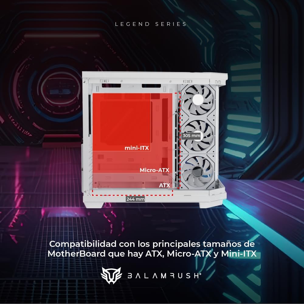
Image 6.1: Motherboard compatibility layout within the case.
- Install the I/O shield (if applicable) into the rear opening of the case.
- Align your motherboard with the pre-installed standoffs. Ensure the standoff locations match your motherboard's form factor (ATX, Micro-ATX, or Mini-ITX).
- Secure the motherboard using the provided screws.
6.3. Storage Device Installation

Image 6.2: Storage drive mounting locations.
- 2.5" SSDs: Mount SSDs to the designated brackets, typically located on the rear of the motherboard tray or in specific drive cages. Secure with screws.
- 3.5" HDDs: Install HDDs into the drive cages located in the lower chamber. Slide the drives into the trays and secure them, often tool-free or with screws.
6.4. Power Supply Unit (PSU) Installation
- Position the PSU in the dedicated compartment at the bottom rear of the case.
- Ensure the PSU fan faces the correct direction (usually downwards for cases with a bottom vent).
- Secure the PSU to the case using the provided screws.
6.5. Graphics Card (GPU) Installation
- Remove the necessary PCIe slot covers from the rear of the case.
- Insert your graphics card into the appropriate PCIe slot on the motherboard.
- Secure the graphics card to the case using screws.
6.6. Cooling System Installation

Image 6.3: Fan and liquid cooling radiator placement options.
- The case comes with four pre-installed ARGB fans.
- Additional fans or liquid cooling radiators can be installed in designated locations (top, front, rear, bottom) as per the specifications. Refer to Image 6.3 for compatible sizes.
- Secure fans and radiators using appropriate screws.
6.7. Cable Management

Image 6.4: Cable routing through the dedicated management space.
- Utilize the 90mm cable management space behind the motherboard tray to route power and data cables.
- Use the provided cable ties to bundle and secure cables, ensuring they do not obstruct airflow or interfere with components.
6.8. Connecting Front Panel I/O
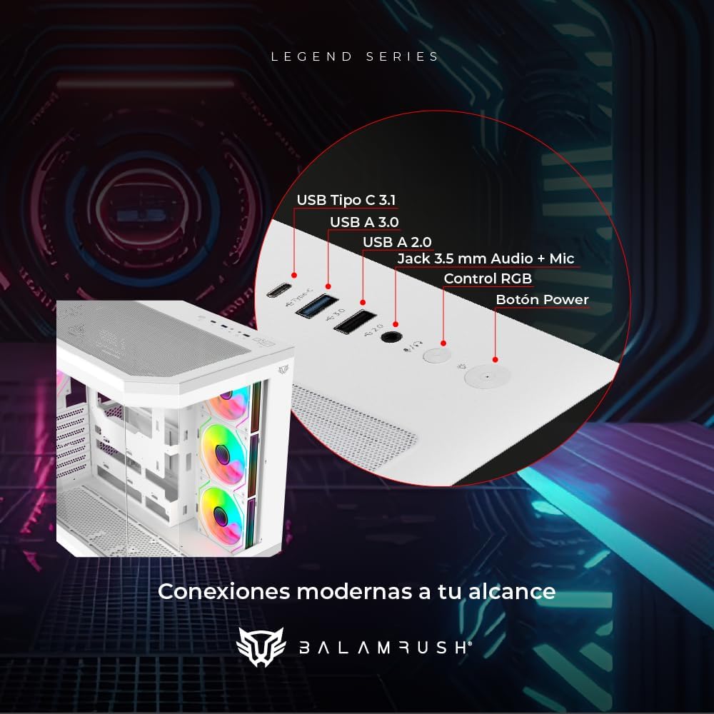
Image 6.5: Front panel I/O connections.
- Connect the front panel cables (USB Type-C, USB 3.0, USB 2.0, HD Audio, Power Switch, Reset Switch, RGB Control) to their corresponding headers on your motherboard. Refer to your motherboard manual for exact header locations.
- Ensure all connections are secure.
7. Operating Instructions
7.1. Powering On
After all components are installed and cables are connected, replace the side panels. Connect your monitor, keyboard, mouse, and power cable. Press the power button on the front panel to start your system.
7.2. ARGB Fan Control
The pre-installed ARGB fans can be controlled via the dedicated RGB control button on the front panel. Press the button to cycle through various lighting modes and colors. If your motherboard supports ARGB synchronization, you may also connect the fans to the motherboard's ARGB header and control them via the motherboard's software.
8. Maintenance
- Dust Filters: Regularly clean the removable dust filters (if present) to maintain optimal airflow and prevent dust buildup inside the case.
- Case Exterior: Wipe the exterior surfaces with a soft, damp cloth. Avoid abrasive cleaners or solvents that may damage the finish.
- Tempered Glass: Clean tempered glass panels with a microfiber cloth and a glass cleaner specifically designed for electronics.
- Internal Cleaning: Periodically use compressed air to remove dust from internal components and fans. Ensure the system is powered off and unplugged before cleaning.
9. Troubleshooting
- System Does Not Power On:
- Check all power connections, including the PSU to the wall outlet, PSU to motherboard, and front panel power switch header.
- Ensure the PSU switch is in the 'ON' position.
- Fans Not Spinning / RGB Not Working:
- Verify that all fan and ARGB cables are correctly connected to the motherboard or a dedicated fan/RGB controller.
- Check motherboard BIOS/UEFI settings for fan control.
- Ensure the RGB control button on the front panel is functioning.
- No Display Output:
- Ensure your monitor is connected to the graphics card (GPU) and not the motherboard's integrated graphics ports (unless you are using integrated graphics).
- Reseat the graphics card and RAM modules.
10. Warranty and Support
For warranty information and technical support, please refer to the warranty card included with your product or visit the official Balam Rush website. Keep your proof of purchase for warranty claims.