BENNTOP BP5500W48V
BENNTOP 5500W 48V Hybrid Solar Inverter User Manual
Model: BP5500W48V
1. Introduction
This manual provides detailed instructions for the installation, operation, and maintenance of your BENNTOP 5500W 48V Hybrid Solar Inverter. Please read this manual thoroughly before installation and use to ensure proper function and safety.

Figure 1: BENNTOP 5500W 48V Hybrid Solar Inverter with its detachable LCD control panel.
Product Features:
- 5500W Pure Sine Wave Inverter: Converts 48V DC to 230V AC.
- Integrated MPPT Solar Charger: 120A MPPT controller with an optimal working voltage range of 60V-500VDC and a maximum PV open circuit voltage of 500Vdc. Supports up to 6500W PV power.
- Multi-functional Design: Combines inverter, solar charger, and battery charger functions.
- Multiple Charging Modes: Four selectable modes: Solar Priority, Utility Priority, Solar and Utility Hybrid, and Solar Only.
- Multiple Output Modes: Three selectable modes: Solar Priority (SUB), Utility Priority (USB), and Solar-Battery-Utility Sequential Priority (SBU).
- Detachable LCD Display: Real-time system data and operational status display. Allows user configuration and provides fault/warning indications.
- Safety Protections: Includes overload, over-temperature, short-circuit, over-current, and over-voltage protection. Features automatic restart upon AC recovery and a cold start function.
- Wide Application: Suitable for home appliances, office equipment, RVs, boats, and camping.
- Remote Monitoring: Supports optional WIFI module for remote monitoring (module sold separately).
2. Safety Instructions
Please observe the following safety precautions during installation, operation, and maintenance of the inverter. Failure to comply may result in electric shock, fire, or serious injury.
- Read all instructions in this manual before operating the unit.
- Do not disassemble the inverter. Refer servicing to qualified personnel.
- Ensure all wiring is correctly connected and securely fastened. Loose connections can cause overheating.
- Install the inverter in a well-ventilated area, away from flammable materials and direct sunlight.
- Do not connect the inverter to a public utility grid without proper grid-tie certification and installation by a licensed electrician. This is an off-grid inverter.
- Always disconnect all power sources (PV, battery, AC input) before performing any maintenance or wiring.
- Wear appropriate personal protective equipment (PPE), including insulated gloves and eye protection, when working with electrical systems.
- Ensure the inverter is properly grounded.
- Be aware that inductive loads require a higher starting power (3 to 5 times the rated power). Select an inverter with adequate capacity.
3. Installation and Setup
3.1 Unpacking and Inspection
Before installation, carefully unpack the unit and inspect it for any damage. Ensure all components are present according to the packing list.
3.2 Mounting the Inverter
Mount the inverter vertically on a sturdy surface. Ensure adequate clearance around the unit for proper ventilation. Avoid mounting in areas with excessive dust, moisture, or high temperatures.
3.3 Wiring Connections
Follow the connection diagram carefully. All wiring must comply with local electrical codes and regulations. Use appropriate wire gauges for all connections.

Figure 2: Typical Inverter Connection Diagram.
- Battery Connection: Connect the 48V battery bank (lead-acid or lithium) to the inverter's battery terminals. Ensure correct polarity.
- PV Input Connection: Connect the solar panel array to the PV input terminals. Observe maximum PV voltage (500Vdc) and power (6500W) limits.
- AC Input Connection: Connect the utility grid or generator AC input to the designated terminals.
- AC Output Connection: Connect your home loads or appliances to the main and second AC output terminals.
- Grounding: Connect the inverter to an earth ground.

Figure 3: Inverter Rear Panel Details and Connections.
3.4 Detachable LCD Panel
The inverter features a detachable LCD control panel. It can be mounted remotely for convenient monitoring and configuration. The WIFI module for remote monitoring is sold separately and connects to the designated network port.
4. Operation
4.1 Initial Power-Up
- Ensure all wiring connections are secure.
- Turn on the battery breaker.
- Turn on the PV array breaker (if applicable).
- Turn on the AC input breaker (if applicable).
- Turn on the inverter's main switch.
- The LCD display will illuminate, showing system status.
4.2 LCD Display and Indicators
The LCD display provides real-time information about the inverter's operation, including input/output voltages, current, power, and battery status. It also shows warning and fault codes.

Figure 4: LCD Display Indicators.
- Red Indicator: Battery Mode
- Utility Mode: (Color not specified, typically blue or green)
- PV Mode: (Color not specified, typically purple or green)
- Use the ESC, UP, DOWN, and ENTER buttons to navigate menus and configure settings.
4.3 Charging Modes
The inverter offers four selectable charging modes to optimize battery charging based on available power sources.

Figure 5: Available Charging Modes.
- Only Solar Charging: Prioritizes solar power for battery charging.
- Utility Priority: Prioritizes utility grid power for battery charging.
- PV Priority: Prioritizes PV power for charging and load.
- Solar+Utility Charging: Uses both solar and utility power for charging.
4.4 Load Output Working Modes
The inverter provides three output modes to manage power delivery to your loads.
Figure 6: Available Load Output Working Modes.
- Solar Priority (SUB): Prioritizes solar power for loads, then battery, then utility.
- Utility Priority (USB): Prioritizes utility power for loads, then solar, then battery.
- SBU Priority (Solar-Battery-Utility): Prioritizes solar, then battery, then utility for loads.
5. Maintenance
Regular maintenance ensures the longevity and optimal performance of your BENNTOP hybrid inverter.
- Cleaning: Periodically clean the inverter's exterior and ventilation openings to prevent dust accumulation. Ensure the unit is powered off before cleaning.
- Connection Checks: Annually inspect all electrical connections for tightness and signs of corrosion. Re-tighten as necessary.
- Battery Inspection: Follow the battery manufacturer's maintenance guidelines for your specific battery type.
- Environmental Check: Ensure the installation environment remains within specified temperature and humidity ranges.
- Firmware Updates: Check the manufacturer's website for any available firmware updates for your model.
6. Troubleshooting
The inverter's LCD display provides fault and warning codes to help diagnose issues. Refer to the specific error codes in the full product manual for detailed troubleshooting steps. Below are general troubleshooting tips:
| Problem | Possible Cause | Solution |
|---|---|---|
| Inverter not turning on | No battery power, loose connections, main switch off. | Check battery voltage, ensure all connections are secure, turn on the main switch. |
| No AC output | Overload, short circuit, low battery voltage, fault code. | Reduce load, check for short circuits, charge battery, check LCD for fault codes. |
| Battery not charging | No PV input, PV voltage too low/high, AC input unavailable, charging mode setting. | Check PV connections, verify PV voltage, check AC input, adjust charging mode settings. |
| Warning/Fault code displayed | Specific system error. | Note the code and refer to the comprehensive manual for detailed resolution steps. |
If the problem persists after attempting these solutions, please contact BENNTOP customer support.
7. Specifications
| Feature | Specification |
|---|---|
| Model | BP5500W48V |
| Rated Power | 5500W |
| Input Voltage | 48V DC |
| Output Voltage | 230V AC |
| Output Waveform | Pure Sine Wave |
| Max. PV Array Power | 6500W |
| MPPT Operating Voltage Range | 60V - 500V DC |
| Max. PV Open Circuit Voltage | 500V DC |
| Max. MPPT Charge Current | 120A |
| Max. AC Charging Current | 100A |
| Dimensions (L x W x H) | 43 x 35 x 15 cm (16.9 x 13.8 x 5.9 inches) |
| Weight | 9.8 kg (21.6 lbs) |
| Display Type | LCD |
| Battery Compatibility | Lead-acid, Lithium |
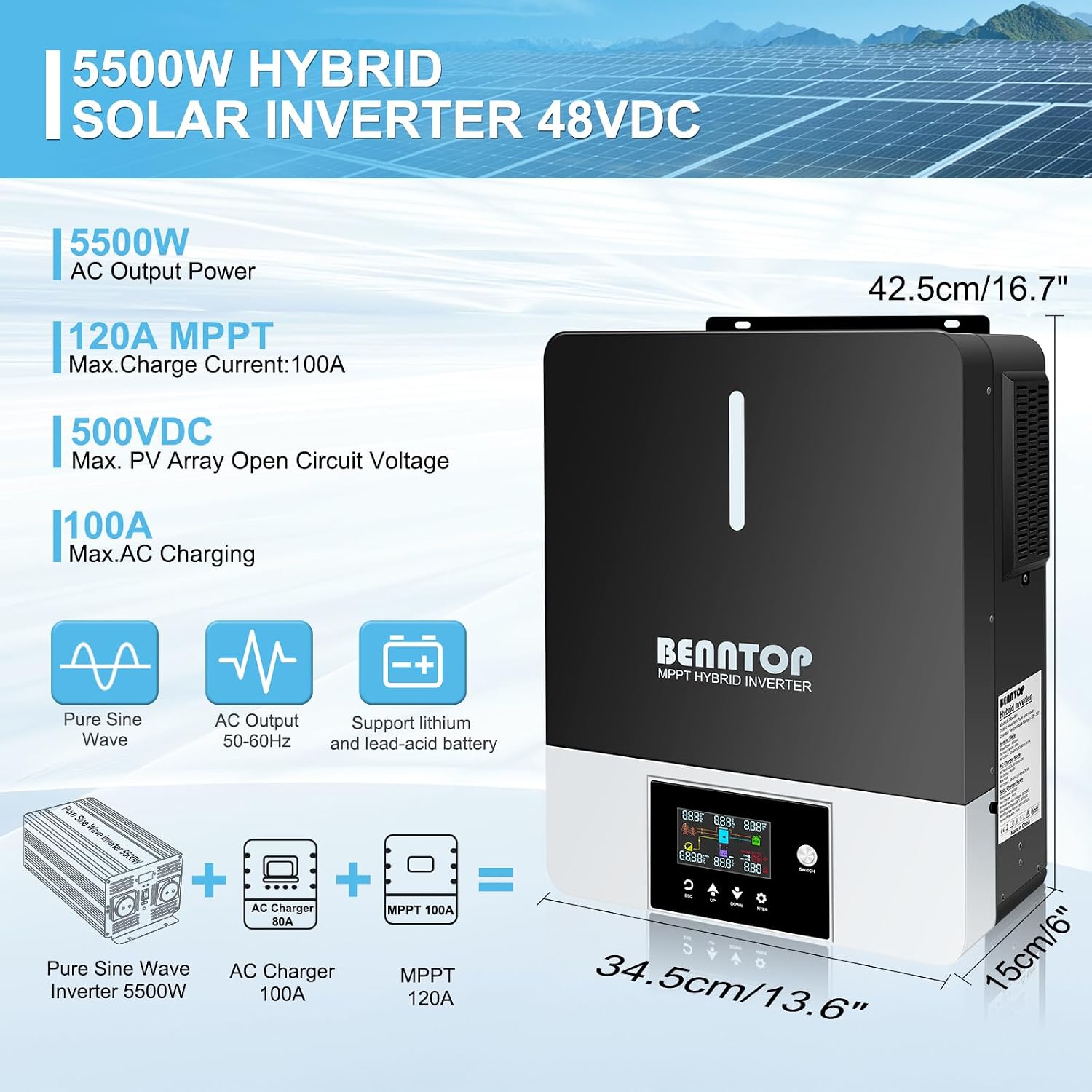
Figure 7: Inverter Dimensions and Key Specifications.
8. Warranty and Support
8.1 Warranty Information
Specific warranty details for the BENNTOP 5500W 48V Hybrid Solar Inverter are typically provided with the product packaging or available on the official BENNTOP website. Please retain your proof of purchase for warranty claims.
8.2 Customer Support
For technical assistance, troubleshooting beyond this manual, or warranty inquiries, please contact BENNTOP customer support through their official channels. Refer to the product packaging or BENNTOP's official website for contact information.
Ask a question about this manual
Ask about setup, troubleshooting, compatibility, parts, safety, or missing instructions. Manuals+ will review the question and use this page’s manual context to help answer it.