bluedery CPE620-2000
bluedery CPE620-2000 Wireless Bridge User Manual
Dual 1Gbps Ethernet Port Point to Point WiFi Extender Long Range Bridge
Product Overview
The bluedery CPE620-2000 is a dual 1Gbps Ethernet port point-to-point wireless bridge designed for long-range outdoor network extension. It operates on the 5.8GHz frequency band and features an 18dBi high-gain antenna, enabling stable signal transmission over distances up to 3 kilometers. This device is suitable for extending network signals between buildings, to remote areas, or for surveillance systems requiring reliable wired connections.

Image: Two bluedery CPE620-2000 wireless bridge units. These units are designed for outdoor use and feature a compact, weather-resistant casing.
Package Contents
Verify that all items are present in the package:
- 2 x Point to Point Starlink WiFi Extender (CPE620-2000 units)
- 2 x PoE Power Adapters
- 2 x Network Cables
- 2 x Mounting Brackets
- 8 x Self-tapping screws and stoppers
- 4 x Bolts and nuts
- 2 x Hose Clamps
- 1 x User Manual (this document)

Image: All components included in the bluedery CPE620-2000 package. This visual guide helps confirm that all necessary parts for installation are present.
Setup Instructions
1. Initial Pairing and Configuration (Bench Setup)
Before outdoor installation, it is recommended to pair and configure the two bridge units indoors to ensure proper functionality.
- Unpack and Connect Power: Open the back cover of both CPE620-2000 units. Connect one end of a network cable to the PoE port of each unit and the other end to the PoE port of the respective PoE power adapter. Plug the power adapters into an electrical outlet.
- Connect to LAN: Connect a second network cable from the LAN port of the first PoE adapter to your router or network switch. Connect a second network cable from the LAN port of the second PoE adapter to a computer or another network device.
- Set Channels:
- On one bridge unit, set the channel switch to 'A' (Master device).
- On the other bridge unit, set the channel switch to 'B' (Slave device).
- Initiate Pairing: Press and hold the black button on both units simultaneously. Continue holding until both LED lights blink simultaneously.
- Observe Pairing Status:
- If no blinking/display persists, switch channels or restart the device.
- The LED displaying a dot indicates the master device, while the other is the slave.
- Wait until either LED stops blinking.
- Press the black button on the other bridge to switch to the same channel.
- Synchronized blinking on the same channel indicates handshake in progress.
- When the flashing stops and the green light turns on, the connection is successful. After successful connection, if the device is restarted, it will automatically connect.
Video: This video demonstrates the initial pairing process for the bluedery wireless bridges, showing how to connect the units, set channels, and confirm successful pairing through LED indicators.
2. Physical Installation
The CPE620-2000 units can be mounted on roofs, walls, or poles. Ensure a clear line of sight between the two units for optimal performance.
- Mounting: Use the provided mounting brackets, screws, bolts, nuts, and hose clamps to secure the units.
- Angle Adjustment: The brackets allow for flexible angle adjustments to ensure precise alignment between the master and slave units.
- Environmental Considerations: The IP65 rating ensures resistance to rain, snow, and dust, making them suitable for various outdoor conditions.

Image: Illustration of wall-mounted and pole-mounted installation options for the wireless bridge units. This highlights the versatility of the mounting hardware.

Image: This diagram emphasizes the necessity of a clear line of sight between the two bridge units for optimal signal transmission, showing how obstructions like walls or trees can impede performance.
Operating Modes and Applications
The bluedery CPE620-2000 supports various operating modes to extend network connectivity.
Point-to-Point Network Extension
This is the primary mode for extending network signals between two distinct locations up to 3KM apart.
- The Master unit connects to your main network (e.g., router).
- The Slave unit receives the signal and provides network access at the remote location.
- Ideal for connecting separate buildings, offices, or homes.
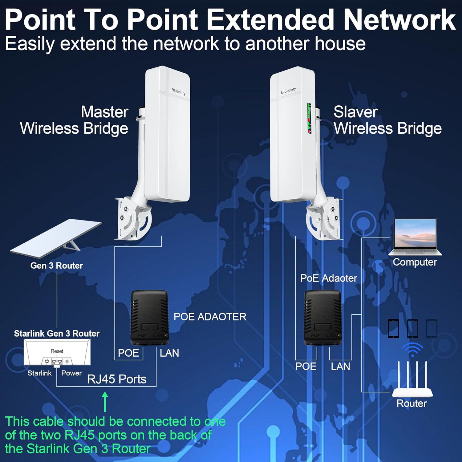
Image: A typical point-to-point network extension scenario, illustrating how the master and slave bridges establish a long-range wireless link to extend internet access.
Point-to-Multiple Point Network Extension
One Master unit can connect to multiple Slave units, extending network access to several remote locations. Ensure the angle between slave units does not exceed 60 degrees for optimal signal integrity.
- Useful for farms, large properties, or industrial sites with multiple remote buildings.

Image: An example of a point-to-multiple-point network setup, demonstrating how a single master unit can distribute network connectivity to several slave units in different directions.
IP Camera Network Extension
The bridges can be used to extend the range of IP camera surveillance systems.
- A Transmitter unit (configured as Slave) connects to IP cameras via a switch.
- A Receiver unit (configured as Master) connects to an NVR or computer for video recording and monitoring.

Image: This diagram illustrates how the wireless bridges can be integrated into an IP camera surveillance system to extend its coverage range.
Starlink Internet Extension
Extend Starlink internet coverage to additional locations, compatible with both Gen 2 and Gen 3 Starlink routers.
- Connect the LAN2 port of the master bridge to an RJ45 port of the Starlink router (Gen 3) or the Starlink Gen 2 Ethernet adapter.

Image: Setup for extending Starlink Gen 2 internet coverage to a remote location using the wireless bridges.

Image: Setup for extending Starlink Gen 3 internet coverage to a remote location using the wireless bridges.
Maintenance
Regular maintenance helps ensure the longevity and optimal performance of your bluedery CPE620-2000 wireless bridges.
- Physical Inspection: Periodically inspect the units and cables for any signs of damage, wear, or corrosion. Ensure all connections are secure.
- Cleaning: Gently wipe the exterior of the units with a soft, damp cloth. Do not use harsh chemicals or abrasive cleaners. Ensure the units are dry before re-applying power.
- Clear Line of Sight: Regularly check that there are no new obstructions (e.g., growing trees, new structures) blocking the line of sight between the two units. Trim foliage if necessary.
- Firmware Updates: Check the manufacturer's website (bluedery Store) for any available firmware updates. Follow the instructions provided with the update carefully.
Troubleshooting
If you encounter issues with your bluedery CPE620-2000, refer to the following common troubleshooting steps:
| Problem | Possible Cause | Solution |
|---|---|---|
| No power/LEDs off | Power adapter not connected or faulty; power outlet issue. | Ensure PoE adapters are securely connected and plugged into a working power outlet. Test the outlet with another device. |
| No connection between units (LEDs not green after pairing attempt) | Incorrect channel setting; units not properly paired; obstructions in line of sight. |
|
| Slow network speed or intermittent connection | Poor signal strength; interference; cable issues; network congestion. |
|
| Cannot access internet at remote location | No connection between units; incorrect network configuration; router issue. |
|
If the problem persists after attempting these solutions, please contact bluedery customer support for further assistance.
Specifications
| Feature | Detail |
|---|---|
| Model Number | CPE620-2000 |
| Brand | bluedery |
| Transmission Range | Up to 3 kilometers (1.9 miles) in open environments |
| Antenna Gain | 18dBi High-Gain Antenna |
| Frequency Band | 5.8GHz |
| LAN Ports | Dual 1Gbps Ethernet Ports |
| Waterproof Rating | IP65 (Dustproof and Waterproof) |
| Power Supply | PoE Power Adapters (included) |
| Mounting Options | Wall-mounted, Pole-mounted (accessories included) |
| Package Dimensions | 13.7 x 13.7 x 2.8 inches |
| Item Weight | 2 pounds |
| Date First Available | May 23, 2024 |

Image: Detailed view of the ports and indicators on the bluedery CPE620-2000 unit, including the dual 1Gbps LAN ports and the channel selection switch.

Image: The bluedery CPE620-2000 unit displayed in a snowy outdoor environment, emphasizing its IP65 dustproof and waterproof rating for durability in adverse weather.
Warranty and Support
For any questions, technical assistance, or warranty inquiries regarding your bluedery CPE620-2000 wireless bridge, please contact bluedery customer support.
You can find contact information and additional resources on the official bluedery Amazon Store page: Visit the bluedery Store.
Please retain your purchase receipt for warranty purposes.
Ask a question about this manual
Ask about setup, troubleshooting, compatibility, parts, safety, or missing instructions. Manuals+ will review the question and use this page’s manual context to help answer it.