1. Introduction
Thank you for choosing the PUWU CT-418PRO Plasma Cutter Welder Combo. This versatile 5-in-1 machine is designed for a wide range of welding and cutting applications, offering MIG, Gasless MIG, Lift TIG, Stick (MMA), and Plasma Cut functions. It features dual voltage compatibility (110V/220V) and an intelligent digital display for precise control. Please read this manual thoroughly before operation to ensure safe and efficient use of the equipment.

Image 1.1: The PUWU CT-418PRO multi-process welding and cutting machine with its included torches.
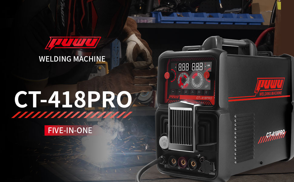
Image 1.2: Visual representation of the five distinct welding and cutting functions available on the CT-418PRO.
2. Safety Information
Operating welding and plasma cutting equipment involves inherent risks. Always prioritize safety to prevent injury or damage to property. Adhere to all local and national safety regulations.
2.1 General Safety Precautions
- Eye Protection: Always wear a welding helmet with appropriate shade lenses for welding and cutting operations.
- Body Protection: Wear flame-resistant clothing, heavy-duty gloves, and safety shoes.
- Ventilation: Ensure adequate ventilation to remove welding fumes and gases. Work in a well-ventilated area or use fume extraction equipment.
- Electrical Safety: Never operate the machine with wet hands or in damp conditions. Ensure proper grounding. Inspect cables and connections for damage before each use.
- Fire Prevention: Keep flammable materials away from the work area. Have a fire extinguisher readily available.
- Work Area: Keep the work area clean and free of clutter. Ensure stable footing.
2.2 Machine Safety Features
The CT-418PRO is equipped with several safety features:
- IP21 Waterproof Rating: Provides protection against vertically falling water drops and solid objects larger than 12.5mm.
- Overheating Auto Shutdown: The machine will automatically shut down if it detects excessive internal temperatures.
- Overload Auto Shutdown: Protects the machine from damage due to excessive current draw.
- Electrostatic Protection: Features a unique coating to help prevent shock transfer.
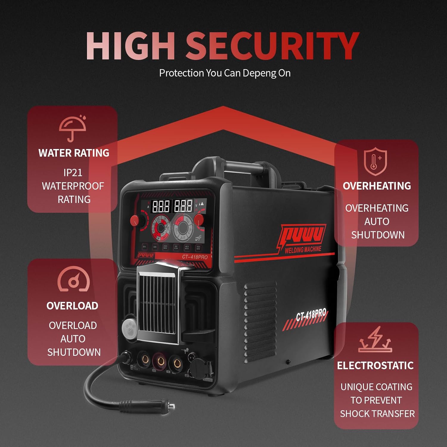
Image 2.1: Overview of the CT-418PRO's integrated safety and protection mechanisms.
3. Product Overview
3.1 Components and Accessories
The PUWU CT-418PRO package includes the following items:
- PUWU CT-418PRO Welder
- 2m Electrode Holder with red 10-25 connector
- 2m Ground Clamp with black 10-25 connector
- 3m TL-L150-10E-S MIG Torch
- 4m WP-17 TIG Torch (Note: Tungsten electrode not included)
- 4m PT31 Plasma Cutting Torch
- Two Wire-Feed Rollers (W-shaped 0.8/0.9, U-shaped 1.2/0.9)
- U.S. Power Cord with 30cm 220V to 110V Conversion Cable
- 2.5m Black Double-threaded Gas Hose
- 3m Transparent Mesh Gas Hose with 0.4m extension (for cutting)
- 3m Transparent Gas Hose (for TIG)
- Air Pressure Regulator
- 3.3m Graphene Liner
- Six Hose Clamps
- Instruction Manual
Note: The spool gun is not included and must be purchased separately if required.
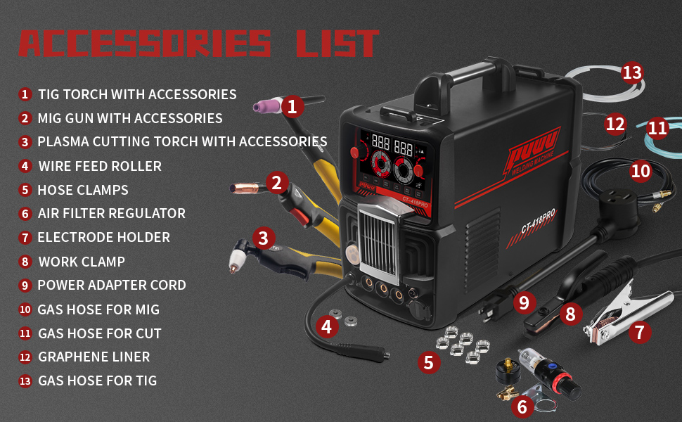
Image 3.1: A visual guide to the comprehensive accessory package included with the CT-418PRO.
3.2 Control Panel Overview
The front panel of the CT-418PRO features an intelligent electronic screen and various controls for selecting welding modes and adjusting parameters.
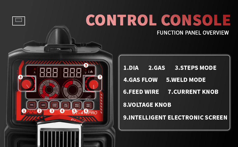
Image 3.2: Detailed view of the control console, highlighting key functions and adjustment knobs.
- DIA: Wire diameter selection.
- GAS: Gas type selection.
- STEPS MODE: Step-by-step adjustment mode.
- GAS FLOW: Gas flow adjustment.
- WELD MODE: Selects welding/cutting process (MIG, TIG, MMA, CUT).
- FEED WIRE: Wire feed speed adjustment.
- CURRENT KNOB: Adjusts welding/cutting current.
- VOLTAGE KNOB: Adjusts welding voltage (primarily for MIG).
- INTELLIGENT ELECTRONIC SCREEN: Displays current settings and parameters.
3.3 Front Panel Connections
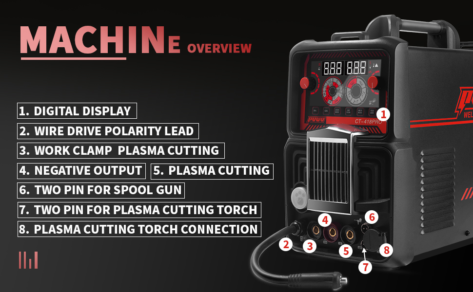
Image 3.3: Front panel connections for various torches and accessories.
- Digital Display: Shows welding/cutting parameters.
- Wire Drive Polarity Lead: For connecting the wire feeder.
- Work Clamp / Plasma Cutting Output: Connection point for the work clamp or plasma cutting torch.
- Negative Output: General negative terminal.
- Plasma Cutting: Dedicated plasma cutting output.
- Two Pin for Spool Gun: Connection for an optional spool gun.
- Two Pin for Plasma Cutting Torch: Control connection for the plasma cutting torch.
- Plasma Cutting Torch Connection: Main power connection for the plasma cutting torch.
4. Setup
Proper setup is crucial for safe and effective operation.
4.1 Power Connection
- The CT-418PRO supports dual voltage: 110V and 220V AC.
- Use the provided power cord and conversion cable as needed.
- Connect the machine to a dedicated circuit with a recommended 40A–50A circuit breaker for stable performance.
- Ensure the power outlet is properly grounded.
4.2 Gas Connection (for MIG, TIG, and Plasma Cut)
- MIG: Connect the 2.5m black double-threaded gas hose from your shielding gas cylinder (e.g., Argon/CO2 mix) to the machine's gas inlet.
- TIG: Connect the 3m transparent gas hose from your Argon cylinder to the machine's gas inlet.
- Plasma Cut: Connect the 3m transparent mesh gas hose with the air pressure regulator to an air compressor. Ensure the air pressure is set according to the cutting parameters.
- Secure all gas hose connections with the provided hose clamps.
4.3 Torch and Work Clamp Connections
- Electrode Holder (Stick/MMA): Connect the electrode holder cable to the appropriate positive (+) terminal and the ground clamp to the negative (-) terminal.
- MIG Torch: Connect the MIG torch to its designated port. Ensure the wire feed roller is correctly installed for the chosen wire diameter (0.8/0.9mm or 1.2/0.9mm).
- TIG Torch: Connect the WP-17 TIG torch to its designated port. Remember to install a tungsten electrode (not included) of the appropriate size.
- Plasma Cutting Torch: Connect the PT31 plasma cutting torch to its dedicated power and control connections on the front panel.
- Work Clamp: Always connect the work clamp securely to the workpiece or a metal workbench that is in direct contact with the workpiece.
5. Operating Instructions
The CT-418PRO offers multiple welding and cutting processes. Select the appropriate mode using the 'WELD MODE' knob on the control panel.
5.1 MIG/Gasless MIG Welding
- Select 'MIG' or 'FLUX' (for gasless MIG) on the 'WELD MODE' selector.
- Adjust wire diameter ('DIA'), gas type ('GAS' if applicable), wire feed speed ('FEED WIRE'), current ('CURRENT KNOB'), and voltage ('VOLTAGE KNOB') according to the material and wire being used.
- Ensure proper polarity for MIG (usually DCEP) or Flux Core (often DCEN).
5.2 Lift TIG Welding
- Select 'TIG' on the 'WELD MODE' selector.
- Connect the TIG torch and Argon gas.
- Adjust the current ('CURRENT KNOB') based on material thickness.
- Initiate the arc by gently touching the tungsten electrode to the workpiece and lifting slightly.
5.3 Stick (MMA) Welding
- Select 'STICK' on the 'WELD MODE' selector.
- Connect the electrode holder and ground clamp.
- Adjust the current ('CURRENT KNOB') according to the electrode type and diameter. The machine supports cellulose electrodes like 6011, 6013, and 7018.
5.4 Plasma Cutting (CUT)
- Select 'CUT' on the 'WELD MODE' selector.
- Connect the plasma cutting torch and air compressor.
- Set the air pressure using the regulator and adjust the cutting current ('CURRENT KNOB').
- Ensure proper standoff distance between the torch tip and the workpiece for optimal cuts.
5.5 Applicable Materials
The CT-418PRO is suitable for welding and cutting various materials, including:
- Carbon Steel
- Sheet Metal
- Square Pipe
- Stainless Steel
- Cast Iron
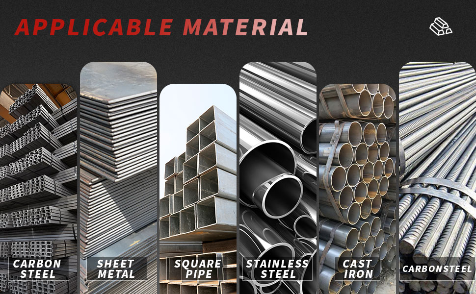
Image 5.1: Examples of materials compatible with the CT-418PRO's welding and cutting capabilities.
6. Maintenance
Regular maintenance ensures the longevity and optimal performance of your CT-418PRO.
- Cleaning: Periodically clean the machine's exterior with a dry cloth. Use compressed air to clear dust from ventilation openings.
- Cable Inspection: Regularly inspect all cables, torches, and connections for wear, cuts, or damage. Replace damaged components immediately.
- Torch Consumables: For plasma cutting, regularly check and replace worn electrodes and nozzles. For MIG, inspect contact tips and liners. For TIG, ensure tungsten electrodes are properly sharpened and free of contamination.
- Air Filter Regulator: For plasma cutting, regularly drain any accumulated moisture from the air filter regulator.
- Storage: Store the machine in a clean, dry environment when not in use.

Image 6.1: The internal cooling system, which benefits from regular cleaning of air vents.
7. Troubleshooting
This section provides solutions to common operational issues.
7.1 Common Issues and Solutions
| Problem | Possible Cause | Solution |
|---|---|---|
| Machine does not power on | No power supply; damaged power cord; internal fault. | Check power connection and circuit breaker. Inspect power cord. Contact support if issue persists. |
| No arc/poor arc initiation | Improper ground connection; incorrect settings; worn consumables; wrong polarity. | Ensure work clamp is securely attached. Verify settings for chosen process. Replace consumables. Check polarity. |
| Wire feed issues (MIG) | Incorrect wire tension; clogged liner; wrong drive roller size; worn contact tip. | Adjust wire tension. Clean or replace liner. Ensure correct drive roller. Replace contact tip. |
| Poor plasma cutting quality | Low air pressure; worn consumables; incorrect current/speed; improper standoff. | Check air pressure and regulator. Replace electrode/nozzle. Adjust current and cutting speed. Maintain correct standoff. |
| Overheat/Overload indicator active | Exceeded duty cycle; insufficient ventilation; internal fault. | Allow machine to cool down. Ensure clear ventilation. Reduce welding duration. |
If you encounter issues not listed here or if solutions do not resolve the problem, please contact PUWU customer support.
8. Specifications
Detailed technical specifications for the PUWU CT-418PRO.
- Model: CT-418PRO
- Manufacturer: PUWU
- Item Weight: 25.6 pounds
- Product Dimensions: 17.7 x 8.5 x 15.22 inches
- Material: Metal, Plastic
- Power Source: AC (110V/220V Dual Voltage)
- Protection Class: IP21
8.1 Welding Parameters
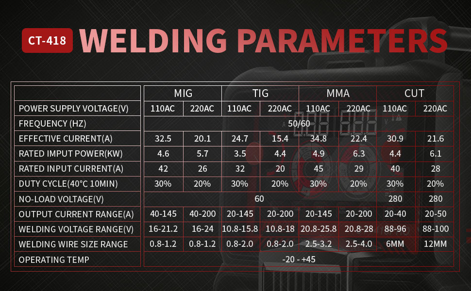
Image 8.1: Detailed welding and cutting parameters for various processes and voltages.
Refer to Image 8.1 for comprehensive welding parameters across MIG, TIG, MMA, and CUT processes for both 110V and 220V inputs. This table provides guidance on effective current, rated input power, duty cycle, output current range, and recommended wire/electrode sizes.
9. Warranty and Support
For warranty information, technical support, or service inquiries, please refer to the warranty card included with your product or contact PUWU customer service directly. Keep your purchase receipt as proof of purchase.
Customer Service Contact: Please visit the official PUWU website or refer to the contact information provided in your product packaging for the most up-to-date support details.


