1. Introduction
This manual provides comprehensive instructions for the installation, operation, and maintenance of the DEWIN 2.2kW Variable Frequency Drive (VFD) inverter. This industrial-grade inverter is designed for precise motor speed regulation, offering high stability and versatility.
The VFD is suitable for a wide range of applications requiring single-phase 220V input and three-phase 220V output, including but not limited to:
- Fans
- Pumps and pump presses
- Compressors
- Conveyors
- Injection molding machines
- Grinders
- Mixers
- Ball mills
Please read this manual thoroughly before installation and operation to ensure safe and efficient use of the device.

Figure 1.1: DEWIN 2.2kW VFD Inverter. This image displays the front view of the VFD unit, highlighting its control panel and a prominent warning label regarding electrical safety.
2. Safety Information
WARNING: Risk of electric shock. Read the user manual before operation. Wait 10 minutes after removing power before servicing. Do not connect AC power to output terminals U/T1, V/T2, or W/T3.
This device is constructed from flame-retardant ABS plastic, offering high impact resistance and heat resistance for safe and reliable performance. Adhere to the following safety guidelines:
- Ensure all power is disconnected before installation, wiring, or maintenance.
- Allow sufficient time for capacitors to discharge after power removal (minimum 10 minutes).
- Only qualified personnel should perform installation and wiring.
- Do not operate the VFD with damaged wiring or components.
- Ensure proper grounding of the VFD and connected motor.
- The VFD features rapid current limiting to prevent overcurrent alarms during sudden loads or interference, enhancing equipment safety.
- Torque limitation functionality helps protect machinery by restricting rotation paths to safe limits.
3. Product Features
The DEWIN VFD inverter incorporates several advanced features for optimal motor control and protection:
- Advanced Control Algorithms: Supports VF control for asynchronous motors, open-loop current vector control, open-loop control for permanent magnet synchronous motors, and open-loop vector control. Achieves high torque, high precision, and a wide speed range.
- Rapid Current Limiting: Prevents frequent overcurrent alarms by quickly limiting current to the protection point during sudden load changes or interference, safeguarding equipment.
- Efficient Cooling System: Equipped with an independent high-speed cooling fan and dedicated air channels for effective heat dissipation, ensuring stable long-term operation and low noise.
- Durable Construction: Made from flame-retardant ABS plastic, providing high resistance to impact and heat.
- Compact and User-Friendly Design: The inverter is compact, features a removable panel, and offers convenient screw terminal connections for easy installation and operation.

Figure 3.1: Key benefits of the DEWIN VFD Inverter. This image illustrates the core advantages of the VFD, including motor protection, energy saving, frequency control, and strong security.
4. Specifications
Refer to the following table for detailed technical specifications of the DEWIN VFD Inverter:
| Parameter | Value |
|---|---|
| Material | Flame retardant ABS plastic |
| Input Rated Voltage | Single-phase 220V |
| Input Rated Frequency | 50/60 Hz |
| Output Rated Voltage | Three-phase 220V |
| Rated Output Current | 10 A |
| Applicable Motor Power | 2.2 kW |
| Output Frequency Range | 0-320 Hz (Low frequency mode) |
| Installation Method | Wall-mounted |
| Protection Level | IP20 |
| Cooling Method | Cooling fan |
| Dimensions (L x W x H) | 140mm x 70mm x 115mm (approx.) |

Figure 4.1: Physical dimensions and key specifications. This image provides a visual representation of the VFD's size and a summary of its technical parameters.
5. Setup and Installation
Proper installation and wiring are crucial for the safe and correct operation of the VFD. Ensure all safety precautions are followed.
5.1 Physical Installation
The DEWIN VFD is designed for wall-mounted installation. Choose a location that is:
- Well-ventilated to allow for proper heat dissipation by the cooling fan.
- Free from excessive dust, moisture, corrosive gases, or direct sunlight.
- Accessible for wiring, operation, and maintenance.
5.2 Wiring Instructions
The VFD requires a single-phase 220V input and provides a three-phase 220V output for the motor. Always ensure power is disconnected before making any wiring connections.

Figure 5.1: Simplified 220V Inverter Wiring. This diagram shows the basic connections: single-phase 220V power supply to the inverter, and the inverter's three-phase output to the motor, along with the ground wire.
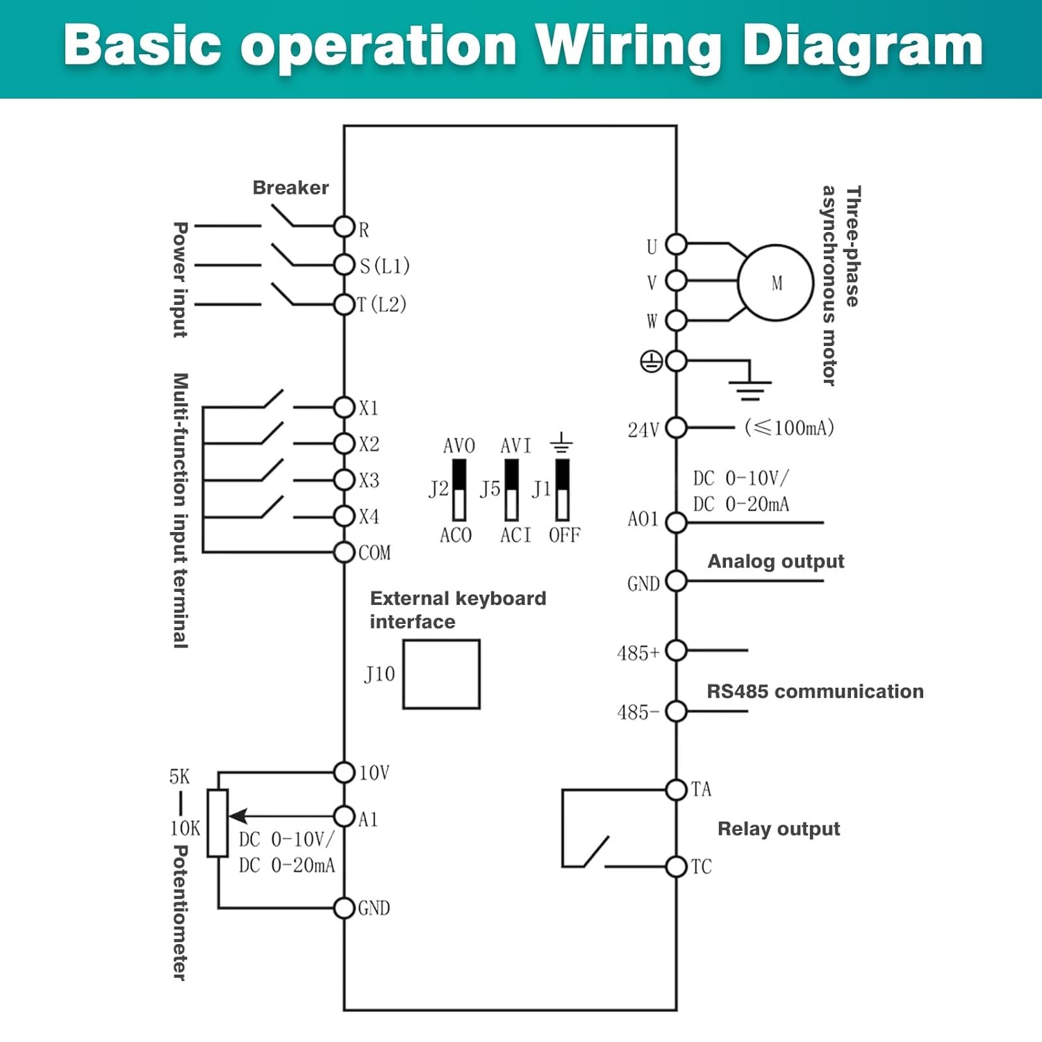
Figure 5.2: Household Electricity AC 220V to Three-Phase Asynchronous Motor Wiring. This image provides a more detailed wiring schematic, including a circuit breaker (switch) for the single-phase AC 220V input, connections to the frequency converter (VFD), and the output to a three-phase asynchronous motor.

Figure 5.3: Basic Operation Wiring Diagram. This schematic illustrates the comprehensive wiring for the VFD, including power input (L1, L2), multi-function input terminals (X1-X4), external keyboard interface (J10), potentiometer connections (10V, A1, GND), analog output (AO1), RS485 communication (485+, 485-), relay output (TA, TC), and the three-phase motor connections (U, V, W) with grounding.
Key Wiring Points:
- Connect the single-phase 220V AC power supply to the input terminals (typically L1 and L2 or R and S).
- Connect the three-phase motor to the output terminals U, V, and W.
- Ensure a proper ground connection for both the VFD and the motor.
- For external control, connect multi-function input terminals (X1-X4) as per your application requirements.
- A potentiometer can be connected to 10V, A1, and GND for analog frequency control.
- RS485 communication terminals (485+, 485-) are available for remote control and monitoring.
6. Operating Instructions
The VFD features an intuitive control panel for setting parameters and controlling motor operation.
6.1 Control Panel Overview

Figure 6.1: Keyboard Operation Instructions. This image labels the various components of the VFD's control panel, including the status display area, numeric up key, frequency setting knob, run key, stop/reset button, parameter data setting button, and value down key.
Control Panel Components:
- Status Display Area: Shows current operating parameters such as frequency (Hz), current (A), and voltage (V).
- PRG (Program) Button: Used to enter or exit parameter setting mode.
- Numeric Up Key (▲): Increases numerical values or navigates through menu options.
- Numeric Down Key (▼): Decreases numerical values or navigates through menu options.
- Frequency Setting Knob: Adjusts the output frequency directly.
- ENTER Button: Confirms selections or parameter changes.
- RUN Button: Starts the motor operation.
- STOP/RST (Reset) Button: Stops the motor or resets the VFD from an error state.
- Parameter Data Setting Button (»): Used to shift between digits when setting parameters or to access specific parameter groups.
6.2 Basic Operation Sequence
- Power On: After ensuring all wiring is correct and secure, apply single-phase 220V power to the VFD. The display will illuminate.
- Set Frequency: Use the Frequency Setting Knob or the Numeric Up/Down keys to set the desired output frequency.
- Start Motor: Press the RUN button to start the motor. The display will show the actual operating frequency and other parameters.
- Stop Motor: Press the STOP/RST button to stop the motor.
- Parameter Adjustment: To change advanced parameters, press the PRG button to enter parameter setting mode. Use the Up/Down keys to navigate, the Parameter Data Setting button to select digits, and ENTER to confirm changes. Refer to the full parameter list in the comprehensive manual for detailed settings.
7. Maintenance
Regular maintenance ensures the longevity and reliable operation of your DEWIN VFD inverter.
- Cleaning: Periodically clean the exterior of the VFD with a soft, dry cloth. Do not use liquid cleaners or solvents.
- Cooling Fan: The VFD is equipped with a cooling fan. Ensure the fan and ventilation openings are free from dust and obstructions to maintain optimal heat dissipation. Clean the fan blades and vents as needed.
- Connections: Periodically check all wiring connections for tightness and signs of corrosion. Loose connections can lead to poor performance or damage.
- Environment: Ensure the operating environment remains within the specified conditions (temperature, humidity, dust level) to prevent premature wear.
Always disconnect power and wait for 10 minutes before performing any maintenance or inspection.
8. Troubleshooting
This section provides general guidance for common issues. For complex problems or error codes not listed here, consult the comprehensive product manual or contact technical support.
- No Power/Display Off: Check the input power supply and circuit breaker. Ensure all power connections are secure.
- Motor Not Running: Verify the RUN command is active. Check motor wiring and ensure the motor is not overloaded or jammed. Confirm frequency settings are appropriate.
- Overcurrent Alarm: This may be due to a sudden load, short circuit, or incorrect motor parameters. The VFD's rapid current limiting feature helps mitigate this, but persistent alarms require investigation. Check motor and load conditions.
- Overvoltage/Undervoltage Alarm: Check the input voltage stability.
- Overheat Alarm: Ensure the cooling fan is operating correctly and ventilation openings are clear. Reduce ambient temperature if necessary.
If an error persists, record the error code displayed (if any) and contact DEWIN technical support for assistance.
9. Warranty and Support
For warranty information, technical support, or service inquiries, please refer to the warranty card included with your product or visit the official DEWIN website. Specific warranty terms and conditions may vary by region and purchase date.
When contacting support, please have your product model number (KDMFZZQAA-GS110208-02) and purchase details readily available.


