
BOSPFJG TPM-01E
TPM-01E Energy Analyzer Multimeter User Manual
Model: TPM-01E | Brand: BOSPFJG
Introduction
The TPM-01E Energy Analyzer is a sophisticated multimeter designed to measure various electrical parameters in 3-phase, 4-wire systems. It provides comprehensive data on load or voltage, current, power factor (cos), active power, reactive power, and tracks minimum and maximum values of the load.
Key Features
- Easy Installation and Operation with a 4x4 Digit Display.
- Measures 3-Phase Voltage and 3-Phase Current.
- User-friendly Menu for navigation.
- Displays Per-Phase Active Powers (P).
- Displays Per-Phase Total Reactive Powers (Q, Inductive and Capacitive).
- Displays Per-Phase Apparent Powers (S).
- Shows Cos (Power Factor) values for each phase.
- Indicates Voltage (V) and Current (I) values for each phase.
- Tracks Total Import and Export Active Energy (kWh) values.
- Records Total Inductive and Capacitive Reactive Energy (kVArh) values.
- Monitors Minimum and Maximum values for various parameters.
- Allows resetting of Energy values.
- Features a Password Protected Menu for security.
Display and Indicators Overview
The TPM-01E features a clear display with various indicators to provide comprehensive information:
- Unit of Value: Indicates the measurement unit for the displayed value.
- L-N: Phase-Neutral Voltage.
- L-L: Phase-Phase Voltage.
- A: Current.
- Cos: Cosinus Fi and Power Factor.
- W: Watt (Active Power). A "-" sign indicates Export Active Power.
- Var: Reactive Power. A "-" sign indicates Capacitive Power.
- VA: Apparent Power.
- kWh: Active Energy.
- kVArh: Reactive Energy. A "-" sign indicates Capacitive Energy.
- Hz: Frequency.
- Phase Indication: Shows which phase the value belongs to (L1, L2, L3).
- Value Type: Specifies the type of value shown (Minimum, Maximum, Average).
- Min.: Indicates minimum values (Period: 2 seconds).
- Max.: Indicates maximum values (Period: 2 seconds).
- Average: Indicates average values (Period: 5 minutes).
- Current Magnitude Indicators: LEDs that light up based on the current drawn from the system.
- L: Lights if current in any phase is 1A or less.
- M: Lights if current in any phase is between 1A and 4A.
- H: Lights if current in any phase is greater than 4A.
Product Views

Figure 1: Front view of the TPM-01E Energy Analyzer, showing the digital display, control buttons, and three current transformers (CTs) for current measurement.
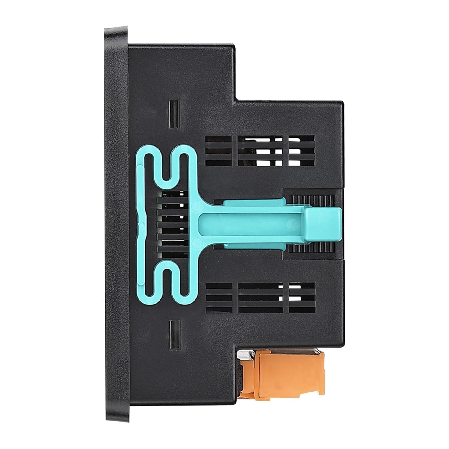
Figure 2: Side view of the TPM-01E Energy Analyzer, highlighting the integrated mounting clip for easy installation and ventilation slots for heat dissipation.
Setup and Installation
The TPM-01E Energy Analyzer is designed for straightforward installation. Please follow these general guidelines:
- Mounting: Securely mount the analyzer in a suitable electrical panel or enclosure using its integrated mounting mechanism. Ensure adequate ventilation around the device.
- Wiring - Voltage Inputs: Connect the 3-phase voltage inputs (L1, L2, L3) and neutral (N) to the corresponding terminals on the analyzer. Refer to the wiring diagram provided with the product for correct phase sequence.
- Wiring - Current Inputs (CTs): Connect the current transformers (CTs) to the respective current input terminals (I1, I2, I3). Ensure the CTs are correctly oriented around the phase conductors as indicated by arrows on the CTs.
- Power Supply: Connect the auxiliary power supply to the analyzer if required (usually derived from the measured voltage lines).
- Initial Power-Up: Once all connections are verified, apply power to the system. The analyzer display should illuminate.
- Configuration: Access the password-protected menu to configure initial settings such as system type (e.g., 3P4W), CT ratios, and any other necessary parameters.
Note: Always ensure power is disconnected before performing any wiring or installation procedures. Consult a qualified electrician if you are unsure about any steps.
Operating Instructions
The TPM-01E features an intuitive menu system for easy operation and data viewing. Use the control buttons (ESC, SET, DOWN, RIGHT) to navigate and interact with the display.
Navigating the Menu:
- SET Button: Used to enter menu options or confirm selections.
- DOWN Button: Used to scroll down through menu options or decrease values.
- RIGHT Button: Used to scroll right or move to the next digit/parameter during setting.
- ESC Button: Used to exit a menu or cancel an operation.
Viewing Measurements:
The display cycles through various measurement parameters. You can use the navigation buttons to manually cycle or hold certain buttons to view specific data points:
- Observe the unit indicators (L-N, L-L, A, W, Var, VA, kWh, kVArh, Hz) to identify the displayed value.
- The phase indicators (L1, L2, L3) show which phase the measurement corresponds to.
- Look for "Min.", "Max.", or "Average" indicators to understand the type of value being shown.
- The L, M, H LEDs provide a quick visual indication of the current magnitude.
Resetting Energy Values:
The analyzer allows for resetting of accumulated energy values (kWh, kVArh). This function is typically password-protected to prevent accidental resets.
- Navigate to the "Energy Reset" option within the menu.
- Enter the password when prompted.
- Confirm the reset operation.
Refer to the full product manual for detailed instructions on menu navigation and specific parameter configurations.
Maintenance
The TPM-01E Energy Analyzer is designed for reliable operation with minimal maintenance. Adhering to these simple guidelines will help ensure its longevity and accuracy:
- Cleaning: Keep the device clean and free from dust and debris. Use a soft, dry cloth for cleaning the display and casing. Avoid abrasive cleaners or solvents.
- Environmental Conditions: Ensure the analyzer operates within its specified environmental conditions (temperature, humidity) to prevent damage.
- Connections: Periodically check all wiring connections to ensure they are secure and free from corrosion. Loose connections can lead to inaccurate readings or device malfunction.
- Firmware Updates: Check the manufacturer's website periodically for any available firmware updates. Follow the provided instructions carefully if an update is necessary.
- Calibration: For critical applications, periodic calibration by a certified laboratory may be required to maintain measurement accuracy. Consult the manufacturer for recommended calibration intervals.
Caution: Do not attempt to open the device or perform internal repairs. Refer all servicing to qualified personnel.
Troubleshooting
If you encounter issues with your TPM-01E Energy Analyzer, consider the following common troubleshooting steps:
| Problem | Possible Cause | Solution |
|---|---|---|
| Display is blank or off. | No power supply; Loose power connection; Device malfunction. | Check power source and connections. Ensure auxiliary power is supplied if required. If problem persists, contact support. |
| Inaccurate readings. | Incorrect wiring (voltage/current); Incorrect CT ratio setting; Faulty CT; Device malfunction. | Verify all wiring connections according to the diagram. Check and correct CT ratio settings in the menu. Inspect CTs for damage. |
| Cannot access menu. | Incorrect password; Buttons not responding. | Ensure correct password is entered. Try pressing buttons firmly. If buttons are unresponsive, contact support. |
| Energy values not accumulating. | Incorrect wiring; Device settings. | Verify current transformer (CT) connections and orientation. Check energy accumulation settings in the menu. |
If the issue persists after attempting these steps, please contact BOSPFJG customer support for further assistance.
Specifications
| Model Number | TPM-01E |
| Brand | BOSPFJG |
| Color | 3CT 1000A |
| Item Weight | 50 Grams (1.76 ounces) |
| Package Dimensions | 1.18 x 0.79 x 0.39 inches |
| Country of Origin | China |
| Date First Available | May 17, 2024 |
Warranty and Support
For warranty information, technical support, or service inquiries regarding your TPM-01E Energy Analyzer, please contact BOSPFJG customer service. Keep your purchase receipt and product model number handy when contacting support.
You can typically find support contact details on the manufacturer's official website or within the product packaging.
Related Documents - TPM-01E
 |
STIL 4857.5 Oil Tester User Manual User manual for the STIL 4857.5 Electronic Oil Tester, providing instructions on features, measurements, configuration, calibration, and safety for assessing frying oil quality. |
 |
YaliTech 825-890 Deep Frying Oil Tester Operating Instructions Detailed operating instructions for the YaliTech 825-890 Deep Frying Oil Tester, covering setup, measurement, calibration, and maintenance for optimal frying oil quality monitoring. |
 |
Testo 270 BT Cooking Oil Tester - Quick Start Guide and Specifications Quick start guide and technical specifications for the Testo 270 BT cooking oil tester. Learn how to operate, calibrate, and understand regulatory compliance for this food safety device. |
 |
Supermicro TPM for X11 User's Manual: Installation and Configuration User's manual for Supermicro TPM modules (AOM-TPM-9670V, AOM-TPM-9670H) for X11 motherboards. Covers installation, BIOS configuration, and Intel TXT provisioning for enhanced system security. |
 |
Testo 270 BT Deep-frying Oil Tester Instruction Manual This instruction manual provides detailed information on the Testo 270 BT, a deep-frying oil tester designed for fast and accurate measurement of cooking oil quality. Learn about its features, operation, maintenance, and troubleshooting to ensure optimal performance and food safety. |
 |
ASRock SPI TPM Module Installation Guide Comprehensive step-by-step guide for installing the ASRock SPI TPM Module. Learn how to prepare a bootable USB drive, navigate the EFI shell, and configure BIOS settings for TPM activation. |
Ask a question about this manual
Ask about setup, troubleshooting, compatibility, parts, safety, or missing instructions. Manuals+ will review the question and use this page’s manual context to help answer it.