Heemol ZK-4KX
Heemol DC Buck Boost Converter ZK-4KX User Manual
Variable Voltage Regulator Module
1. Introduction
This manual provides comprehensive instructions for the Heemol DC Buck Boost Converter ZK-4KX. This versatile module functions as a variable voltage regulator, capable of both stepping up (boost) and stepping down (buck) DC voltage. It features an LCD display for real-time monitoring of input/output parameters and incorporates multiple protection mechanisms for safe operation. Designed for various applications, including laboratory power supplies, LED drivers, and battery charging.
2. Product Features
- Safe Protection: Features input reverse connection protection to prevent damage. No external anti-reverse diode is needed for charging applications. Includes multiple software protection mechanisms with adjustable thresholds, automatically cutting off output if operating parameters exceed safe limits.
- Wide Input/Output Range: Input voltage range of 5-30V DC; output voltage range of 0.5-30V DC.
- High Current & Power: Supports 3A continuous output current (up to 4A with improved heat dissipation). Maximum output power of 35W (up to 50W with improved heat dissipation).
- LCD Display: Clear LCD shows input/output voltage, output current, output power, output capacity, and output time. The module can be configured for default ON/OFF state.
- Efficient Thermal Performance: Designed with a thick heat sink and integrated buck-boost architecture for effective heat dissipation. Features low output ripple and an integrated filter.
- Versatile Applications: Can be used as a general buck/boost module with overcurrent protection, a high-power constant current LED driver module, a solar current controller, or for battery charging.
3. Product Specifications
| Parameter | Value |
|---|---|
| Brand | Heemol |
| Model Number | ZK-4KX |
| Input Voltage | 5.0 - 30V DC |
| Output Voltage | 0.5 - 30V DC |
| Output Current | 3A (continuous), 4A (with enhanced heat dissipation) |
| Output Power | 35W (max), 50W (with enhanced heat dissipation) |
| Dimensions (L x W x H) | Approximately 7.9 x 4.3 x 3.9 cm (3.11 x 1.69 x 1.53 inches). Note: The provided specification of 10x10x10mm is incorrect. Please refer to product images for accurate visual scale. |
| Display | LCD (Voltage, Current, Power, Capacity, Time) |
| Protection | Input reverse connection, adjustable software protection thresholds |
4. Product Overview and Components

This image displays the front of the Heemol ZK-4KX DC Buck Boost Converter, showing the LCD screen, two control buttons (SW and U/I), and the rotary encoder on the right. The screen indicates "OUT 12.00V 0.000A".

This image illustrates the physical dimensions of the ZK-4KX module. The length is approximately 3.11 inches (7.9 cm), width 1.69 inches (4.3 cm), and height 1.53 inches (3.9 cm). The mounting hole distance is 2.79 inches (7.1 cm).

This image highlights the control elements: the "SW" button, "U/I" button, constant current indicator (CC), output indicator (ON), and the rotary encoder.

A detailed table explaining the functions of the SW button, U/I button, and rotary encoder in different operating interfaces (normal, regulating voltage/current, setting parameters).
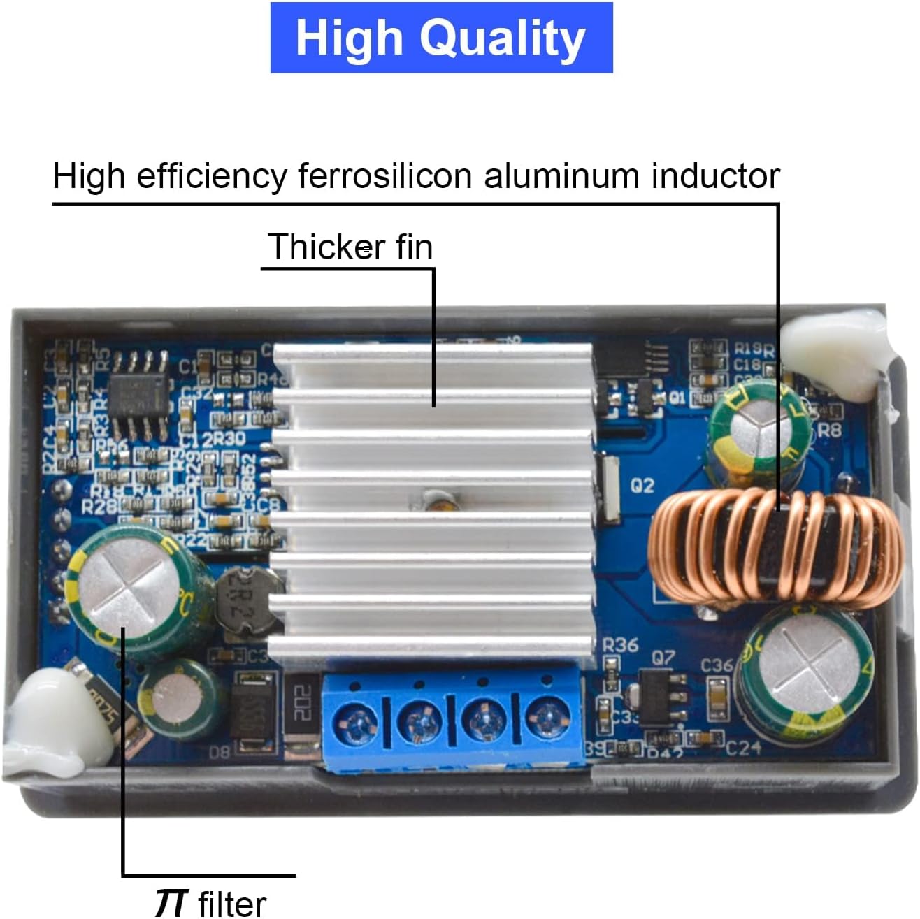
This image shows the internal layout of the module, highlighting the high-efficiency ferrosilicon aluminum inductor, the thicker heat sink for improved thermal performance, and the π filter for reduced output ripple.
5. Setup Instructions
- Power Connection: Connect the DC input voltage (5-30V) to the input terminals labeled "IN+" and "IN-". Ensure correct polarity. The module has reverse connection protection, but proper connection is always recommended.
- Output Connection: Connect your load to the output terminals labeled "OUT+" and "OUT-".
- Initial Power On: Apply power to the input. The LCD will illuminate, displaying the current output voltage and current.
- Mounting (Optional): If permanent installation is required, use the mounting holes on the module. Refer to Figure 4.2 for dimensions.
Important: Always ensure the input voltage is within the specified range (5-30V DC) and that the load does not exceed the module's maximum current (3A continuous, 4A peak) or power (35W max, 50W peak) ratings.
6. Operating Instructions
6.1. Display Modes
The LCD can display various parameters. Use the "SW" button to cycle through different display modes in the normal interface.

This image illustrates the various parameters displayed on the LCD, including output voltage, input voltage, temperature, output current, output power, output capacity (AH), and output time (H). The "SW" button cycles through these displays.
- Upstream Display: Output Voltage (OUT V), Input Voltage (IN V), Temperature (°C).
- Downstream Display: Output Current (A), Output Power (W), Output Capacity (AH), Output Time (H).
6.2. Key Functions
Refer to Figure 4.4 (Key Description Table) for a comprehensive overview. Key functions are:
- SW Button:
- Short Press: Toggles the display parameters (e.g., current, power, capacity, time).
- Long Press: Toggles between input voltage display and output voltage display.
- U/I Button:
- Short Press: Enters the voltage/current regulation interface.
- Long Press: Enters the parameter setting interface.
- Rotary Encoder:
- Short Press: Toggles output ON/OFF.
- Left Rotation: Decreases the adjusted parameter value.
- Right Rotation: Increases the adjusted parameter value.
6.3. Adjusting Voltage and Current
- Enter Regulation Mode: Short press the "U/I" button to enter the voltage/current regulation interface. The parameter being adjusted will blink.
- Select Parameter: Short press the "U/I" button again to switch between adjusting output voltage and constant current value.
- Adjust Value: Rotate the rotary encoder to increase or decrease the selected value. A short press of the rotary encoder can shift the adjustment digit.
- Exit Regulation Mode: Long press the "U/I" button to exit the regulation interface and return to the normal display.
6.4. Setting Parameters (Protection Thresholds, Default ON/OFF)
- Enter Setting Mode: Long press the "U/I" button to enter the parameter setting interface.
- Navigate Parameters: Short press the "SW" button to cycle through the parameters available for setting (e.g., over-voltage protection, over-current protection, default output state).
- Adjust Value: Rotate the rotary encoder to change the value of the selected parameter. A short press of the rotary encoder can shift the adjustment digit.
- Exit Setting Mode: Long press the "U/I" button to save changes and exit the setting interface.
7. Maintenance
- Cleaning: Keep the module clean and free from dust. Use a soft, dry cloth for cleaning. Do not use liquids or abrasive cleaners.
- Ventilation: Ensure adequate airflow around the module, especially if operating at higher currents or power levels, to facilitate heat dissipation.
- Connections: Periodically check all input and output connections to ensure they are secure and free from corrosion.
- Storage: Store the module in a dry, cool environment when not in use.
8. Troubleshooting
| Problem | Possible Cause | Solution |
|---|---|---|
| No display/No output |
|
|
| Output voltage/current unstable |
|
|
| Module gets hot quickly |
|
|
| Output automatically cuts off |
|
|
9. Warranty and Support
Heemol products are designed for reliability and performance. For specific warranty information, please refer to the product packaging or the retailer's terms of sale. If you encounter any issues or require technical assistance, please contact your point of purchase or the manufacturer's customer support channels.
Please retain your proof of purchase for warranty claims.