
1. Introduction
This manual provides detailed instructions for the operation and maintenance of the Cousopo FG-200 DDS Function Signal Generator. This compact and versatile device is designed for electronic circuit testing, debugging, frequency characteristic analysis, and impulse response measurements, making it suitable for various professional and educational applications. Please read this manual thoroughly before using the device to ensure proper and safe operation.
2. Product Overview
2.1 Key Features
- Compact size with comprehensive functions and simple operation.
- Portable design, powered by DC4-9V (DC5V recommended with adapter) or a 3.7V lithium battery.
- Capable of generating 15 types of waveforms, including Sine, Square, Triangle, Forward Sawtooth, Reverse Sawtooth, ECG, Exponential Rise, Exponential Fall, Lorentz Pulse, Gauss Pulse, Sinc Pulse, Half-wave, Full-wave, Schumann, and Noise.
- Sine wave frequency range: 0.01Hz to 500.00kHz (output amplitude may decrease at higher frequencies).
- Other waveform frequency range: 0.01Hz to 100.00kHz (higher frequencies possible with relaxed distortion requirements).
- Frequency resolution: 0.01Hz.
- Sine wave distortion: Less than 1% below 1kHz, less than 0.5% above 1kHz.
- Maximum output amplitude: 10V (Peak-to-Peak).
- Output impedance: 50 ohms.
- Integrated filter function for sine and pulse waveforms.
- Square wave output is suitable for oscilloscope attenuator and probe pulse characteristic adjustments.
2.2 Package Contents
Please verify that all items listed below are present in your package:
- 1 x FG-200 DDS Function Signal Generator Unit
- 1 x USB to 3.5mm Power Cable
- 1 x BNC to Alligator Clip Cable

Figure 1: FG-200 DDS Function Signal Generator unit with its power cable and BNC to alligator clip output cable.
3. Setup
- Power Connection: Connect the USB to 3.5mm power cable to the DC 5V input port on the side of the FG-200 unit. Connect the USB end to a suitable power source (e.g., computer USB port, USB power adapter, or a 3.7V lithium battery power supply). Ensure the power supply meets the DC4-9V requirement.
- Signal Output Connection: Connect the BNC end of the BNC to alligator clip cable to the "DDS OUT" BNC connector on the front panel of the FG-200. Connect the alligator clips to your test equipment, such as an oscilloscope, ensuring proper polarity (red for signal, black for ground).

Figure 2: Connecting the BNC output cable to the FG-200 unit.

Figure 3: DC 5V power input port on the side of the FG-200 unit.
4. Operating Instructions
4.1 Panel Description
Familiarize yourself with the controls on the front panel of the FG-200 unit:
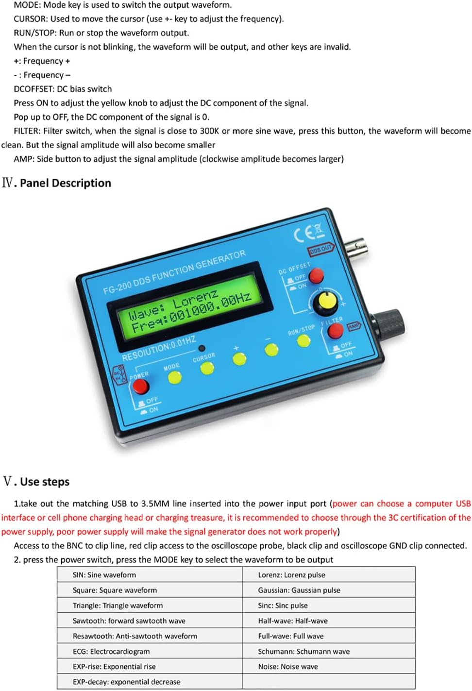
Figure 4: Front panel layout and control descriptions.
- POWER (ON/OFF Switch): Toggles the device power.
- MODE Button: Used to switch between different output waveforms.
- CURSOR Button: Moves the cursor on the display to select which digit of the frequency to adjust.
- '+' / '-' Buttons: Adjusts the selected frequency digit (when the cursor is blinking).
- RUN/STOP Button: Starts or stops the waveform output. When the cursor is not blinking, the waveform will be output, and other keys are inactive.
- DC OFFSET (ON/OFF Switch): Toggles the DC bias component of the signal. When set to OFF, the DC component is 0.
- FILTER (ON/OFF Switch): Activates or deactivates the filter. When the signal frequency is close to 300KHz or a sine wave, activating the filter can clean the signal, though it may also reduce amplitude.
- AMP (Rotary Knob): Adjusts the output signal amplitude. Turn clockwise to increase amplitude.
4.2 Waveform Selection and Adjustment
- Power On: Switch the POWER button to 'ON'. The display will light up.
- Select Waveform: Press the MODE button repeatedly to cycle through the available waveforms. The current waveform type will be displayed on the screen.
- Adjust Frequency:
- Press the CURSOR button to make a digit of the frequency blink. This indicates the digit that can be adjusted.
- Use the '+' and '-' buttons to increase or decrease the value of the blinking digit.
- Repeat pressing CURSOR and '+' / '-' to set the desired frequency.
- Adjust Amplitude: Rotate the AMP knob clockwise to increase the output amplitude and counter-clockwise to decrease it.
- Adjust DC Offset: Use the DC OFFSET switch to turn the DC bias on or off.
- Apply Filter: Use the FILTER switch to turn the signal filter on or off, especially useful for sine and pulse waveforms at higher frequencies.
- Start/Stop Output: Press the RUN/STOP button to begin or pause the waveform output.
4.3 Available Waveforms
The FG-200 supports the following waveform types:
| Waveform Type | Description |
|---|---|
| Sine wave | Standard sinusoidal waveform. |
| Square wave | Rectangular pulse waveform. |
| Triangle wave | Linear ramp up and down. |
| Forward sawtooth wave | Linear ramp up, then sharp drop. |
| Reverse sawtooth wave | Sharp rise, then linear ramp down. |
| ECG (Electrocardiogram) | Simulates an ECG signal. |
| EXP-rise (Exponential rise) | Waveform with exponential increase. |
| EXP-decay (Exponential decrease) | Waveform with exponential decrease. |
| Lorentz pulse | A specific pulse shape. |
| Gaussian pulse | Bell-shaped pulse. |
| Sinc pulse | Sine cardinal function pulse. |
| Half-wave | Rectified half-wave. |
| Full-wave | Rectified full-wave. |
| Schumann wave | Simulates Schumann resonance. |
| Noise wave | Random signal. |
4.4 Operational Demonstration Video
Watch this video for a visual guide on selecting waveforms, adjusting frequency, and observing the output on an oscilloscope.
Video: Demonstration of waveform selection and frequency adjustment using the FG-200 DDS Function Signal Generator connected to an oscilloscope.

Figure 5: Examples of waveforms generated by the FG-200 as displayed on an oscilloscope.
5. Maintenance
- Cleaning: Use a soft, dry cloth to clean the exterior of the device. Avoid using abrasive cleaners or solvents.
- Storage: Store the device in a cool, dry place away from direct sunlight and extreme temperatures.
- Battery Care: If using a lithium battery, ensure it is charged regularly and not left completely discharged for extended periods.
- Handling: Handle the device with care to prevent physical damage. Avoid dropping or subjecting it to strong impacts.
6. Troubleshooting
- No Output Signal:
- Ensure the device is powered on and the power indicator is lit.
- Verify that the output cable is securely connected to both the FG-200 and the test equipment.
- Check if the RUN/STOP button is in the 'RUN' state (waveform output active).
- Confirm that the test equipment (e.g., oscilloscope) is correctly configured to receive the signal.
- Distorted Waveform:
- Check the frequency setting. At very high frequencies, some waveforms may exhibit increased distortion.
- Try activating the FILTER for sine or pulse waves to clean the signal.
- Ensure the amplitude is not set too high, causing clipping on the test equipment.
- Incorrect Frequency Display/Output:
- Verify that the correct digit is selected for adjustment using the CURSOR button.
- Ensure the '+' and '-' buttons are pressed correctly to change the frequency.
7. Specifications
| Parameter | Value |
|---|---|
| Output Waveforms | 15 types (Sine, Square, Triangle, Sawtooth, ECG, etc.) |
| Power Supply | DC4-9V (DC5V recommended), 3.7V Lithium Battery |
| Current Consumption | 180mA at 5V |
| Sine Wave Frequency Range | 0.01Hz - 500.00kHz |
| Other Waveform Frequency Range | 0.01Hz - 100.00kHz |
| Frequency Resolution | 0.01Hz |
| Sine Distortion | <1% below 1kHz, <0.5% above 1kHz |
| Output Amplitude | Max 10V (P-P) |
| Output Impedance | 50 ohms |
| Package Dimensions | 6.3 x 4.92 x 1.38 inches |
| Item Weight | 9 ounces |
| Manufacturer | Cousopo |
8. Warranty and Support
For warranty information, technical support, or service inquiries, please contact the seller or manufacturer directly. Keep your purchase receipt as proof of purchase.
