HBGKMHHLV-DC36V-STROKE30MM
User Manual
DC 36V/48V 1500N Linear Actuator
Model: HBGKMHHLV-DC36V-STROKE30MM
Introduction
This manual provides essential information for the safe and efficient operation of your DC 36V/48V 1500N Linear Actuator. Please read this manual thoroughly before installation, operation, or maintenance to ensure proper use and to prevent damage or injury.
Safety Information
- Always disconnect power before performing any installation, maintenance, or troubleshooting.
- Ensure the power supply voltage matches the actuator's specified voltage (DC 36V or 48V).
- Do not exceed the rated thrust or speed of the actuator.
- Avoid continuous operation for extended periods. The actuator requires a rest period of 8 minutes after 2-4 minutes of continuous operation to prevent overheating.
- Keep hands and clothing clear of moving parts during operation.
- Install the actuator securely to a stable surface using appropriate mounting hardware.
Product Overview
The Linear Actuator is designed to provide precise linear motion for various applications, capable of pushing, pulling, lifting, and lowering objects. It features a robust design with a high thrust capacity.

Figure 1: Main view of the DC 36V/48V 1500N Linear Actuator. This image shows the compact design of the actuator, highlighting its motor and main body.
Key Features:
- High Thrust: 1500N capacity for heavy-duty applications.
- Variable Stroke Lengths: Available in various stroke lengths from 30mm to 800mm.
- Speed: Operates at 7mm/s.
- Voltage Options: Compatible with DC 36V and 48V power supplies.
- Integrated Limit Switches: Features self-contained limit switches for automatic stop at stroke ends.
- Optional Hall Sensor: Can be equipped with a Hall sensor for position feedback.
- Magnetic Switch Compatibility: Designed to work with magnetic switches.
- PLC System Integration: Suitable for matching with PLC systems for automated control.
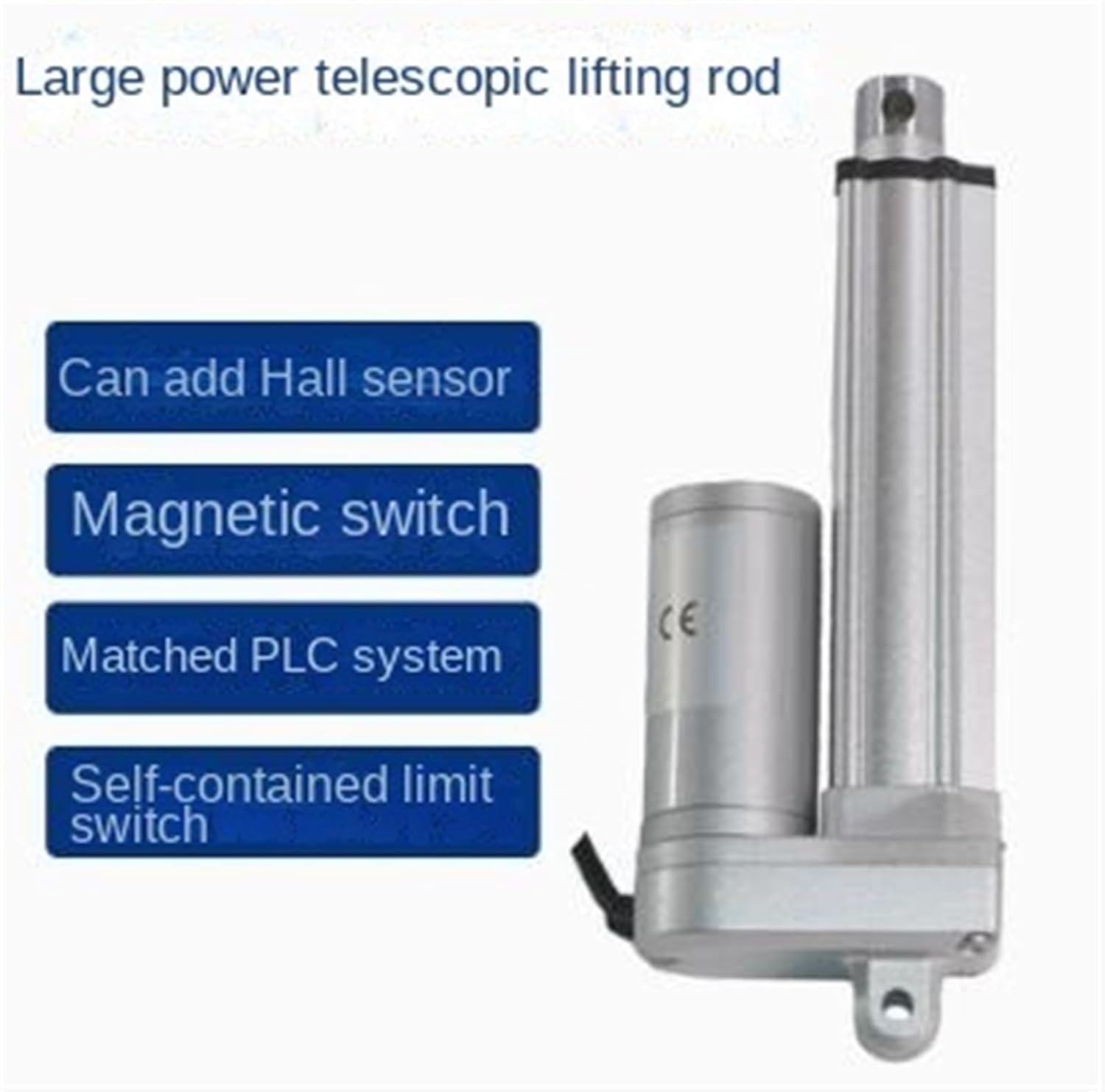
Figure 2: Illustration of key features including optional Hall sensor, magnetic switch, PLC system compatibility, and self-contained limit switch.
Specifications
| Parameter | Value |
|---|---|
| Product Name | Linear Actuator |
| Voltage | DC 36V/48V |
| Thrust | 1500N |
| Speed | 7mm/s |
| Stroke Range | 30mm - 800mm |
| Item Model Number | HBGKMHHLV-DC36V-STROKE30MM |
| Manufacturer | Generic |
| Country of Origin | China |

Figure 3: Detailed dimensions of the linear actuator, showing full retraction and full extension lengths for a 30mm stroke model.

Figure 4: Technical drawings illustrating various component dimensions and mounting hole details for the linear actuator.
Setup and Installation
Mounting the Actuator:
The linear actuator should be mounted securely using its designated mounting points. Ensure the mounting surface is stable and capable of supporting the actuator's weight and thrust force during operation.

Figure 5: Diagram showing the installation dimensions, including minimum installation distance and how to calculate retractable and received lengths based on travel.
Wiring Diagram:
Connect the actuator to a compatible DC 36V or 48V power supply according to the following diagram. Pay close attention to polarity to ensure correct operation and prevent damage.

Figure 6: Circuit schematic diagram for the linear actuator, showing connections for the motor, limit switches, and power input. Includes formulas for minimum installation distance based on stroke length.
Stroke Length Calculation Examples:
Understanding the relationship between stroke length and the actuator's physical dimensions is crucial for proper integration. The following examples illustrate how to calculate fully retracted and fully open center distances based on different travel lengths.

Figure 7: Examples demonstrating how to calculate the fully retractable and fully open center distances for various stroke lengths (100MM, 400MM, 1000MM), including special reminders for different travel ranges.
Operating Instructions
Once installed and wired correctly, the linear actuator can be operated by applying the appropriate DC voltage to its terminals. Reversing the polarity of the voltage will reverse the direction of the actuator's movement.
Duty Cycle:
It is important to adhere to the recommended duty cycle to ensure the longevity of the actuator. The actuator is not designed for continuous long-term operation. After 2-4 minutes of continuous use, allow the actuator to rest for at least 8 minutes before resuming operation. Failure to observe this duty cycle may lead to overheating and premature failure of the unit.
Maintenance
The linear actuator is designed for minimal maintenance. However, periodic checks can help ensure optimal performance and extend its lifespan.
- Cleaning: Keep the actuator body and rod clean from dust, dirt, and debris. Use a soft, dry cloth for cleaning. Avoid using harsh chemicals or solvents.
- Lubrication: The internal components are pre-lubricated and generally do not require additional lubrication. If the actuator is exposed to harsh environments, consult the manufacturer for specific lubrication guidelines.
- Connections: Periodically check all electrical connections for tightness and ensure there are no frayed or damaged wires.
- Mounting: Verify that the mounting hardware remains secure and that there is no excessive play or vibration during operation.
Troubleshooting
| Problem | Possible Cause | Solution |
|---|---|---|
| Actuator does not move | No power, incorrect wiring, faulty power supply, internal damage. | Check power connections and supply voltage. Verify wiring polarity. Test power supply. If problem persists, contact support. |
| Actuator moves slowly or with reduced force | Insufficient voltage, excessive load, internal friction. | Ensure correct voltage. Reduce load if exceeding rated thrust. Check for obstructions. |
| Actuator overheats | Exceeding duty cycle, excessive load, poor ventilation. | Observe recommended duty cycle (2-4 min operation, 8 min rest). Reduce load. Ensure adequate airflow around the motor. |
| Actuator makes unusual noise | Mechanical obstruction, worn internal components. | Check for any foreign objects obstructing movement. If noise persists, contact support. |
Warranty Information
This product is covered by a standard manufacturer's warranty against defects in materials and workmanship. The specific terms and duration of the warranty may vary. Please retain your proof of purchase for warranty claims. For detailed warranty information, refer to the product packaging or contact the seller directly.
Customer Support
If you encounter any issues or have questions regarding the installation, operation, or maintenance of your linear actuator, please contact the seller or manufacturer for assistance. Provide your product model number (HBGKMHHLV-DC36V-STROKE30MM) and a detailed description of the issue when seeking support.
For further information, you may visit the product page on Amazon.