U UNNI B0D3TGC4MX
U UNNI Indoor Outdoor Thermometer Hygrometer Wireless Weather Station User Manual
Model: B0D3TGC4MX
1. Introduction
Thank you for choosing the U UNNI Indoor Outdoor Thermometer Hygrometer Wireless Weather Station. This device provides accurate, real-time monitoring of indoor and outdoor temperature and humidity, along with additional environmental indices. Please read this manual thoroughly before use to ensure proper operation and longevity of your device.
2. Package Contents
Verify that all items are present in your package:
- 1 x Main Display Unit (Indoor Thermometer/Hygrometer)
- 1 x Remote Sensor (Outdoor Thermometer/Hygrometer)
- 1 x User Manual
- (Batteries are NOT included)
3. Key Features
- High-precision Swiss-made Sensirion sensor for accurate readings.
- Wireless transmission up to 330 ft (100m) with 30-second updates.
- Large, clear backlit LCD display for easy readability.
- Displays indoor/outdoor temperature and humidity.
- Includes Heat Index, Dew Point Index, and Mold Index.
- Supports up to 3 remote sensors (additional sensors sold separately).
- Tabletop or wall-mountable design.

Figure 3.1: Overview of the main display unit and remote sensor, illustrating key features.
4. Product Overview
4.1 Main Display Unit

Figure 4.1: Front view of the main display unit.
- Outdoor Temperature & Humidity Display
- Weather Forecast Icon
- Outdoor Index (Heat, Dew, Mold)
- Indoor Temperature & Humidity Display
- RF Signal Indicator
- Backlight Button (Top)

Figure 4.2: Back view of the main display unit with buttons and battery compartment.
- INDEX Button: Cycles through Heat Index, Dew Point Index, and Mold Index.
- MEM Button: Displays maximum/minimum temperature and humidity readings.
- CH Button: Selects sensor channel (1, 2, or 3) or initiates manual search for sensors.
4.2 Remote Sensor

Figure 4.3: Main display unit and remote sensor.
- LED Indicator: Flashes when transmitting data.
- Channel Switch: Inside battery compartment, set to 1, 2, or 3.
- Reset Button: Inside battery compartment, used for resetting the sensor.
5. Setup
5.1 Battery Installation
For the Remote Sensor:
- Open the battery compartment cover on the back of the remote sensor.
- Insert 2 x AA batteries (not included) according to the polarity markings (+/-).
- Set the channel switch (1, 2, or 3) inside the battery compartment. Ensure each sensor uses a different channel if you have multiple.
- Close the battery compartment cover. The LED indicator will flash once, indicating power.
For the Main Display Unit:
- Open the battery compartment cover on the back of the main display unit.
- Insert 3 x AAA batteries (not included) according to the polarity markings (+/-).
- Close the battery compartment cover. The display will power on and begin searching for the remote sensor.

Figure 5.1: Battery installation for the main unit and remote sensor.
5.2 Sensor Placement
For optimal performance and accurate readings:
- Place the main display unit indoors, away from direct sunlight, heat sources, or vents.
- Position the remote sensor outdoors in a shaded, dry location, protected from direct rain and prolonged sun exposure. While the sensor has an IPX4 waterproof rating, protection from harsh elements will extend its lifespan and accuracy.
- Ensure the remote sensor is within the 330 ft (100m) transmission range of the main unit. Walls and other obstructions may reduce this range.

Figure 5.2: Recommended remote sensor placement for accuracy and protection.
5.3 Synchronization
After installing batteries in both units, the main display unit will automatically attempt to connect with the remote sensor. The RF signal indicator on the display will flash during this process. Once connected, the outdoor temperature and humidity will appear on the display. If connection fails:
- Press and hold the "CH" button on the main unit for 3 seconds to initiate a manual search.
- Ensure the remote sensor is powered on and within range.
- If still unsuccessful, remove and reinsert batteries in both units, starting with the remote sensor, then the main unit.
6. Operating Instructions
6.1 Display Overview
The main display unit shows the following information:
- Outdoor Section: Displays current outdoor temperature, humidity, and RF signal strength.
- Weather Forecast: Icons indicate predicted weather conditions (sunny, partly cloudy, rainy, etc.).
- Outdoor Index: Shows Heat Index, Dew Point Index, or Mold Index.
- Indoor Section: Displays current indoor temperature and humidity.
6.2 Button Functions
- Backlight Button (Top of unit): Briefly touch the light icon on the top of the main unit to activate the backlight for approximately 10 seconds, improving visibility in low-light conditions.
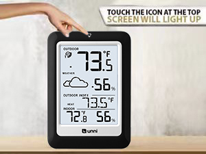
Figure 6.1: Activating the display backlight.
- INDEX Button: Press repeatedly to cycle through the Outdoor Index displays: Heat Index, Dew Point Index, and Mold Index. The selected index will remain displayed.

Heat Index

Dew Point Index

Mold Index
- MEM Button: Press once to view the maximum temperature and humidity recorded since the last reset. Press again to view the minimum readings. Press and hold for 3 seconds to clear the recorded MAX/MIN values. These values typically reset every 24 hours from the time batteries were first inserted.
- CH Button: Press to switch between different remote sensor channels (if multiple sensors are used). Press and hold for 3 seconds to manually search for remote sensors.
6.3 Temperature Unit Selection (°F/°C)
To switch between Fahrenheit (°F) and Celsius (°C), locate the small switch or button inside the battery compartment of the main display unit. Toggle it to your preferred unit.
6.4 Weather Forecast
The weather station analyzes atmospheric pressure changes to predict weather conditions for the next 12-24 hours. The icons displayed are: Sunny, Partly Cloudy, Cloudy, and Rainy. This is a prediction and may not always match current conditions.
7. Maintenance
- Cleaning: Wipe the display unit and sensor with a soft, damp cloth. Do not use abrasive cleaners or solvents.
- Battery Replacement: Replace batteries in both units when the low battery indicator appears on the display. Always replace all batteries at once.
- Sensor Care: Ensure the remote sensor remains protected from extreme weather conditions to prolong its life and maintain accuracy.
8. Troubleshooting
| Problem | Possible Cause | Solution |
|---|---|---|
| No outdoor reading on display. | No connection between main unit and sensor; low sensor battery; sensor out of range. | Check sensor batteries. Press and hold "CH" button on main unit to re-sync. Move sensor closer to main unit. Ensure sensor channel matches main unit. |
| Inaccurate readings. | Sensor exposed to direct sunlight/rain; interference; unit not calibrated (initial setup). | Relocate sensor to a shaded, protected area. Allow units to stabilize for 24 hours after setup. Avoid placing near large metal objects or electronics. |
| Display is dim or blank. | Low main unit battery. | Replace AAA batteries in the main display unit. |
| Weather forecast is incorrect. | Weather forecast is a prediction based on pressure changes, not real-time. | This is normal. The forecast is an approximation for the next 12-24 hours and may not always align with current conditions. |
9. Specifications
| Feature | Detail |
|---|---|
| Indoor Temperature Range | +14.2°F to +122°F (-9.9°C to +50°C) |
| Outdoor Temperature Range | -58°F to +158°F (-50°C to +70°C) |
| Indoor/Outdoor Humidity Range | 1% to 99% RH |
| Temperature Accuracy | +/-0.5°F (+/-0.2778°C) |
| Humidity Accuracy | +/-2% RH |
| Wireless Transmission Range | Up to 330 ft (100m) in open air |
| Update Frequency | Every 30 seconds |
| Main Unit Power | 3 x AAA batteries (not included) |
| Remote Sensor Power | 2 x AA batteries (not included) |
| Sensor Waterproof Rating | IPX4 |
| Display Type | LCD with Backlight |
| Dimensions (Main Unit) | Approx. 4.8 x 3.5 inches (Height x Width) |
10. Warranty and Support
The U UNNI Indoor Outdoor Thermometer Hygrometer Wireless Weather Station comes with a one-year warranty from the date of purchase. This warranty covers manufacturing defects but does not include batteries or damage caused by misuse, accident, or unauthorized modifications.
For technical support, troubleshooting assistance, or warranty claims, please contact U UNNI customer service through the retailer where the product was purchased or visit the official U UNNI website for contact information. Please have your model number (B0D3TGC4MX) and purchase date ready when contacting support.
Online Resources: For additional information and FAQs, please visit the U UNNI Store on Amazon.