1. Introduction
This manual provides detailed instructions for the installation, operation, and maintenance of your GOOD STORY WB501C Wireless Bridge 3-Pack. This 5.8GHz outdoor wireless bridge system is designed to establish stable and high-speed network connections over long distances, up to 3 kilometers. It supports both Point-to-Point (PTP) and Point-to-Multipoint (PTMP) configurations, making it suitable for extending network coverage to outbuildings, barns, garages, or for surveillance systems.
The devices are pre-configured for ease of use, requiring minimal setup to get your network operational.

Figure 1: GOOD STORY WB501C Wireless Bridge 3-Pack

Figure 2: Key Features of the WB501C Wireless Bridge
2. Safety Information
Please read all safety instructions before installation and operation. Failure to follow these guidelines may result in injury or damage to the device.
- Outdoor Installation: Ensure the devices are securely mounted to prevent falling in high winds.
- Power Over Ethernet (PoE): Use only the provided PoE injector. Using a third-party PoE injector with incorrect voltage (e.g., 12V or 48V instead of 24V) can damage the unit.
- Cable Requirements: Use Ethernet cables rated for outdoor use and PoE to ensure reliable power and data transmission, especially for long runs.
- Lightning Protection: Consider additional lightning protection for outdoor installations, especially in areas prone to electrical storms.
- Environmental Conditions: While weatherproof, avoid submerging the device in water. Ensure proper ventilation if installed in an enclosed space.
3. Package Contents
Verify that all items are present in your package:
- GOOD STORY WB501C Wireless Bridge Units (3 units for 3-Pack)
- PoE Injectors (3 units for 3-Pack)
- Quick Start Guide
Note: Mounting brackets are not included and must be purchased separately.

Figure 3: Wireless Bridge Unit and PoE Injector
4. Product Overview
Each WB501C unit features a robust, weatherproof design suitable for outdoor deployment. Key components and indicators are as follows:
4.1. Physical Ports and Indicators

Figure 4: WB501C Ports and Controls
- DC Power: For direct power input (typically not used with PoE).
- PoE/LAN 1: Primary Ethernet port for power and data. Connects to the PoE injector's PoE port.
- PoE/LAN 2: Secondary Ethernet port for data passthrough or connecting another network device.
- Master/Slave Switch: Toggles the unit's role between Master and Slave.
- Reset/Channel Button: Used for factory reset or changing the wireless channel.
- LED Indicators: Provide status information for power, signal strength, and LAN activity.
4.2. Weatherproof Design
The WB501C is designed for outdoor use, featuring a weatherproof and durable casing that can withstand various environmental conditions, including rain, heat, and cold.

Figure 5: Weatherproof Features
5. Setup and Installation
The GOOD STORY WB501C units are pre-configured for a hassle-free setup. Follow these steps for installation:
5.1. Mounting the Units
- Choose Locations: Select suitable outdoor locations for your Master and Slave units. Ensure a clear line of sight between units for optimal performance.
- Secure Mounting: Mount the units securely using appropriate mounting hardware (not included). The concave curve on the back of the antennas is designed for pole or rounded surface mounting.
- Alignment: Precise alignment is crucial for long-distance links. Aim the units directly at each other. The vertical beam has a 15-degree range, requiring accurate height placement.
5.2. Connecting the Devices (Point-to-Point Example)
For a basic Point-to-Point setup to extend your network:
- Master Unit Setup:
- Set one unit as the Master using the Master/Slave switch.
- Connect an Ethernet cable from your existing router/network (LAN port) to the LAN port of the Master's PoE injector.
- Connect another Ethernet cable from the PoE port of the Master's PoE injector to the PoE/LAN 1 port on the Master unit.
- Plug the PoE injector into a power outlet.
- Slave Unit Setup:
- Set the other unit as the Slave using the Master/Slave switch.
- Connect an Ethernet cable from the PoE port of the Slave's PoE injector to the PoE/LAN 1 port on the Slave unit.
- Connect another Ethernet cable from the LAN port of the Slave's PoE injector to a Wi-Fi router or network device at the remote location.
- Plug the PoE injector into a power outlet.

Figure 6: Point-to-Point Real World Scenario

Figure 7: Point-to-Point Network Extension Diagram
5.3. Point-to-Multipoint Setup
For Point-to-Multipoint configurations, one Master unit can connect to multiple Slave units (up to 8). The Master unit broadcasts the signal, and each Slave unit receives it. This is ideal for surveillance systems or extending network to several remote buildings.
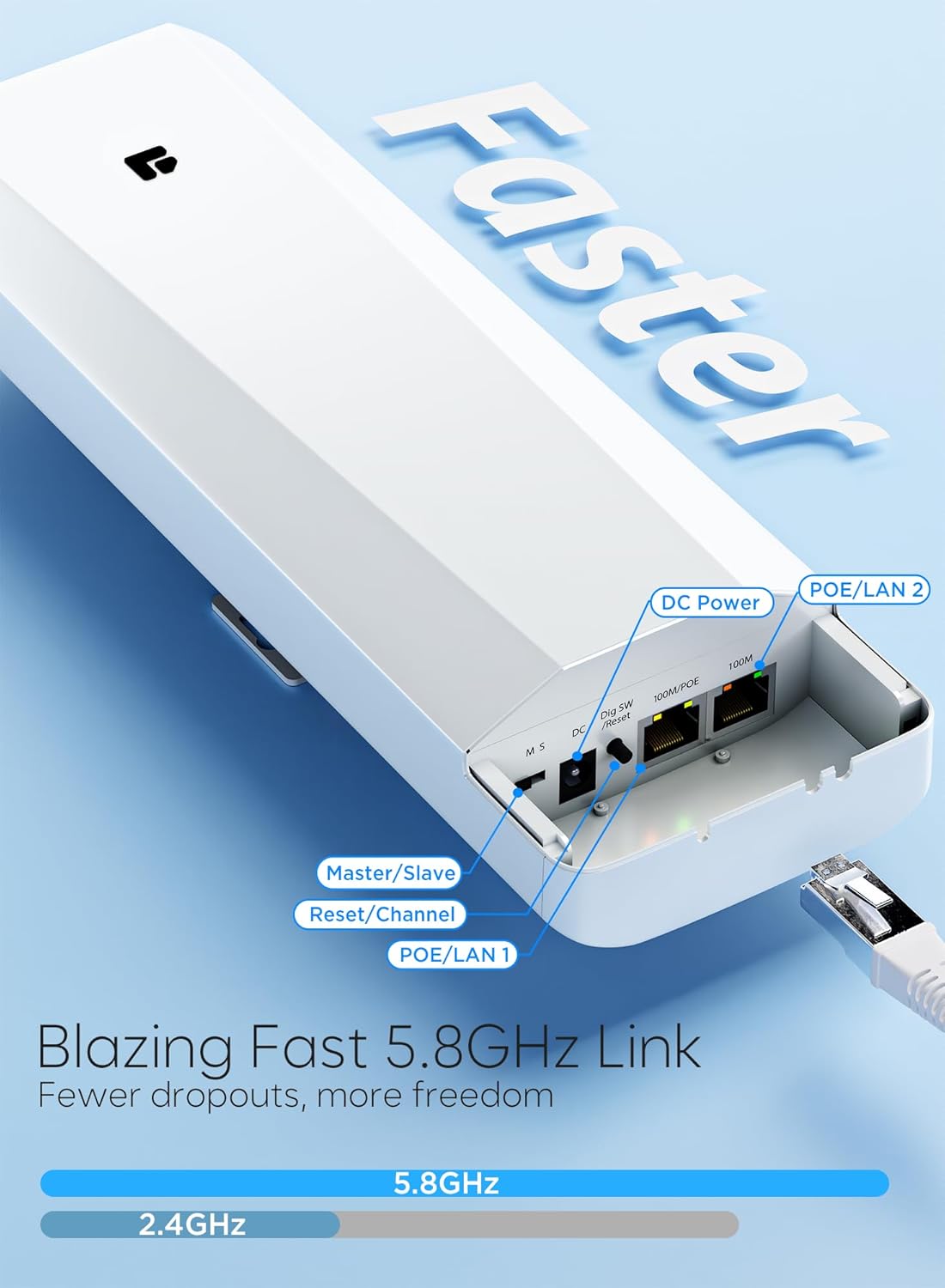
Figure 8: Point-to-Multipoint Surveillance Setup

Figure 9: Point-to-Multipoint Network Extension Diagram
5.4. Starlink Network Extension
The WB501C can also be used to extend a Starlink internet connection to a remote location.

Figure 10: Starlink Network Extension
6. Operation
Once powered on and aligned, the units will automatically establish a wireless link. The LED indicators on the side of each unit provide visual feedback on the connection status and signal strength.
6.1. LED Indicators
- Power LED: Indicates the unit is receiving power.
- Signal Strength LEDs: Multiple LEDs illuminate to show the strength of the wireless link. More illuminated LEDs indicate a stronger signal.
- LAN LEDs: Indicate activity on the Ethernet ports.
6.2. Cascade Connection
For extending networks beyond a single hop or bypassing obstacles, multiple wireless bridge pairs can be cascaded. This involves connecting a Slave unit to a second Master unit via an Ethernet cable, which then transmits the signal to another Slave unit.

Figure 11: Cascade Wireless Bridge Setup
7. Maintenance
The WB501C is designed for minimal maintenance due to its durable, weatherproof construction.
- Cleaning: Periodically inspect the units for dirt, dust, or debris accumulation, especially on the front panel. Clean with a soft, damp cloth. Do not use harsh chemicals or abrasive cleaners.
- Cable Inspection: Regularly check Ethernet cables for signs of wear, damage, or degradation, particularly if exposed to harsh weather or wildlife.
- Firmware Updates: Check the manufacturer's website for any available firmware updates to ensure optimal performance and security.
8. Troubleshooting
If you encounter issues with your wireless bridge, refer to the following troubleshooting tips:
- No Power/LEDs Off: Ensure the PoE injector is properly connected to a power outlet and the Ethernet cable from the PoE injector's PoE port is securely connected to the unit's PoE/LAN 1 port.
- Digital Channel Display Shows '--': This indicates the antenna is underpowered. Verify you are using the provided 24V PoE injector. Ensure your Ethernet cable is rated for PoE and is not excessively long for its gauge (e.g., Cat6a 28 AWG has a maximum reliable run of about 300 feet).
- No Link/Weak Signal:
- Line of Sight: Confirm there is a clear line of sight between the Master and Slave units. Obstacles like trees or buildings can severely degrade signal quality.
- Alignment: Re-align the units carefully. Even slight adjustments can significantly impact signal strength over long distances. The vertical beam is narrow (15 degrees).
- Distance: While rated for 3KM, environmental factors can reduce effective range.
- Intermittent Connection: Check for environmental interference (e.g., other 5.8GHz devices). Ensure cables are securely connected and undamaged. Heavy fog or rain can temporarily decrease signal strength on the 5.8GHz band.
- No Internet at Remote Location:
- Verify the Master unit is receiving internet from your main router.
- Ensure the Slave unit is properly connected to a Wi-Fi router or network device at the remote location.
- Check the network configuration of the remote Wi-Fi router/device.
- Mounting Hardware: The product does not include mounting brackets. If you are experiencing issues with stability, ensure you have appropriate and robust mounting hardware.
9. Specifications
| Feature | Specification |
|---|---|
| Model Number | WB501C |
| Brand | GOOD STORY |
| Frequency Band | 5.8GHz (Single-Band) |
| Wireless Standard | 802.11n |
| Transmission Distance | Up to 3KM (9800ft) |
| Connectivity Technology | Wi-Fi |
| Special Features | Internet Security, LED Indicator, Weatherproof |
| Compatible Devices | Laptop, Personal Computer, Security Camera, Smart Television |
| Recommended Uses | Business, Residential |
| Item Weight | 3.76 pounds (for the pack) |
| Package Dimensions | 12.83 x 11.18 x 2.83 inches |
10. Warranty Information
Specific warranty details for the GOOD STORY WB501C Wireless Bridge are typically provided at the point of purchase or within the product packaging. Please retain your proof of purchase for warranty claims. For detailed warranty terms and conditions, please refer to the official GOOD STORY website or contact customer support.
11. Support
For further assistance, technical support, or inquiries, please visit the official GOOD STORY store or contact their customer service:
- GOOD STORY Amazon Store: Visit the GOOD STORY Store
- Manufacturer Contact: Refer to the product packaging or the official website for direct contact information.