1. Introduction
The XTUGA SY-1000 Pro UHF Wireless Antenna Distribution System is designed to optimize and expand the capabilities of professional wireless microphone setups. It efficiently distributes UHF signals across multiple receivers, ensuring stable and extended signal coverage for various live events. This system supports a wide UHF frequency spectrum (400-950MHz) and can achieve a signal reach of up to 2600 feet (approximately 800 meters), making it suitable for stage performances, weddings, live shows, and other demanding environments.
This manual provides essential information for the proper setup, operation, and maintenance of your SY-1000 Pro system to ensure optimal performance and longevity.
2. Product Overview and Components
The XTUGA SY-1000 Pro system includes the main antenna distribution amplifier unit, active directional antennas, and necessary accessories for installation and operation.
2.1 Included Components
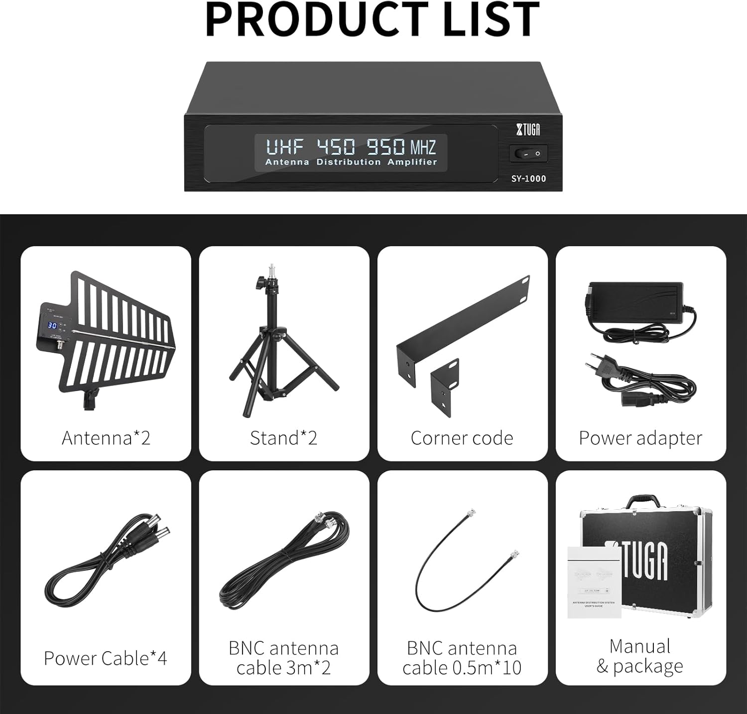
Figure 2.1: All components included in the XTUGA SY-1000 Pro package.
- Antenna Distribution Amplifier Unit (SY-1000)
- Active Directional Antennas (x2)
- Antenna Stands (x2)
- Corner Code (for rack mounting)
- Power Adapter
- Power Cables (x4)
- BNC Antenna Cables (3m x2)
- BNC Antenna Cables (0.5m x10)
- User Manual
2.2 System Components Identification

Figure 2.2: Labeled components of the SY-1000 Pro system.
- Bright screen (on distribution unit)
- Switch (power)
- Power Socket
- DC Power Jack (for external devices)
- Antenna A Input
- Antenna B Input
- MIC A Antenna Interface (Output for Receiver A)
- MIC B Antenna Interface (Output for Receiver B)
- Select key up (on antenna)
- Bright screen (on antenna)
- Select key down (on antenna)
- Signal Receiving Wing (antenna paddle)
- Bracket Interface (for antenna stand)
- Bracket (antenna stand)
3. Setup Instructions
Proper setup is crucial for optimal performance of your XTUGA SY-1000 Pro system.
3.1 Antenna Placement Precautions

Figure 3.1: Antenna placement guidelines.
- Height: The installation height of the antenna should be higher than 1.8 meters for best signal reception.
- Distance: Antennas need to be placed within the range of the signal transmitter (e.g., wireless microphone) and the periphery should be greater than 1.5 meters from any major obstructions. Ensure a clear line of sight.
- Interference: Keep antennas away from large metal objects and various signal interference sources (e.g., large electronic equipment, power lines).
- Environment: When used outdoors, place the antenna in a dry position to protect it from moisture.
3.2 System Connections
- Mount Antennas: Attach the active directional antennas to their respective stands using the bracket interface. Position them according to the guidelines in Section 3.1.
- Connect Antennas to Distribution Unit: Use the provided BNC antenna cables (3m) to connect the two active antennas to the 'Antenna A' and 'Antenna B' input ports on the rear of the SY-1000 distribution amplifier unit.
- Connect Receivers: Connect your wireless microphone receivers to the 'MIC A Antenna Interface' and 'MIC B Antenna Interface' output ports on the SY-1000 using the shorter BNC antenna cables (0.5m). Each unit supports the connection of up to 4 wireless receivers with 2 antennas.
- Power Connection: Connect the power adapter to the 'Power Socket' on the SY-1000 unit and then to a suitable power outlet.
- DC Power Output: The SY-1000 features 4 DC power ports delivering 12V direct current, which can be used to power compatible wireless receivers or other accessories. Use the provided power cables for these connections.
- Cascade Port (Optional): For expanding your system, the cascade port allows connection to additional receivers or a second antenna distribution system.
3.3 Powering On
After all connections are securely made, press the 'Switch' button on the front panel of the SY-1000 unit to power on the system. The bright screens on both the distribution unit and the antennas will illuminate.
4. Operating Instructions
Once the system is set up, follow these instructions for operation.
4.1 Gain Level Adjustment

Figure 4.1: Antenna gain level adjustment controls.
The active antennas feature 31 adjustable gain levels. This allows you to compensate for signal loss that may occur over long coaxial cable runs. Use the 'Select key up' and 'Select key down' buttons next to the bright screen on each antenna to adjust the gain level. Monitor your receiver's signal strength indicators to find the optimal gain setting for your environment.
4.2 Signal Reception
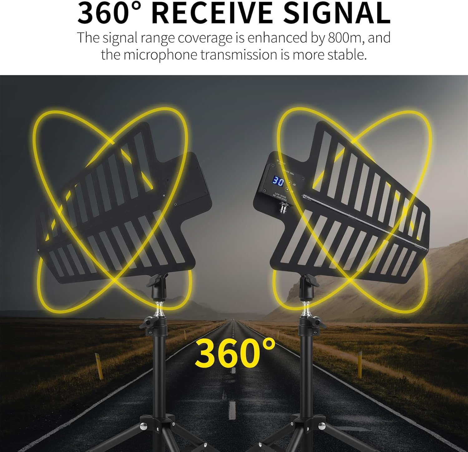
Figure 4.2: 360° signal reception.
The active directional antennas are designed to enhance signal reception across a 360-degree range, ensuring stable microphone transmission. The system's professional circuit design helps eliminate reception dead zones, providing reliable coverage for your event.
4.3 UHF Frequency Compatibility

Figure 4.3: UHF frequency compatibility.
The SY-1000 Pro system is fully compatible with the UHF frequency band from 400-950MHz. This broad compatibility ensures it can be used with a wide range of U-segment wireless microphones and multi-channel wireless systems.
4.4 Long-Distance Signal Transmission

Figure 4.4: Long-distance signal transmission capability.
The system is engineered for robust signal transmission over long distances, extending signal reach up to 2600 feet (approximately 800 meters) while maintaining stability. This makes it ideal for large venues and outdoor events.
5. Maintenance
To ensure the longevity and reliable performance of your XTUGA SY-1000 Pro system, follow these maintenance guidelines:
- Cleaning: Regularly wipe the distribution unit and antennas with a soft, dry cloth. Avoid using abrasive cleaners or solvents.
- Environmental Protection: Keep the system away from excessive dust, moisture, and extreme temperatures. If used outdoors, ensure it is protected from rain and direct sunlight.
- Cable Inspection: Periodically check all BNC and power cables for any signs of wear, damage, or loose connections. Replace damaged cables immediately.
- Storage: When not in use for extended periods, store the system in its original packaging or a protective case in a cool, dry place.
- Antenna Care: The antennas are crafted from aviation-grade material with anti-oxidation and anti-corrosion properties. However, avoid physical impact or bending the signal receiving wings.
6. Troubleshooting
If you encounter issues with your XTUGA SY-1000 Pro system, refer to the following common problems and solutions:
- No Signal or Weak Signal to Receivers:
- Ensure the SY-1000 unit is powered on and its indicator lights are active.
- Check all BNC cable connections between the antennas, the distribution unit, and the receivers. Ensure they are secure.
- Verify antenna placement according to Section 3.1. Ensure they are elevated, have a clear line of sight, and are not obstructed by metal objects.
- Adjust the gain levels on the active antennas (Section 4.1) to compensate for cable loss.
- Confirm that the wireless microphones are powered on and operating on compatible frequencies.
- Intermittent Signal Dropouts:
- Check for potential sources of interference in the environment (e.g., Wi-Fi routers, other wireless devices, large LED screens). Try to relocate the antennas or the interference source.
- Ensure the operating range is not exceeded (2600ft maximum).
- Re-check antenna gain settings.
- Power Issues (Unit Not Turning On):
- Verify that the power adapter is correctly connected to the SY-1000 and a working power outlet.
- Check the power cable for any damage.
- Ensure the power switch on the SY-1000 is in the 'ON' position.
7. Specifications
| Feature | Specification |
|---|---|
| Model | SY-1000 Pro |
| Brand | XTUGA |
| Antenna Type | UHF Wireless, Active, Directional |
| Frequency Range | 400-950MHz |
| Maximum Range | 2600 Feet (approx. 800 meters) |
| Antenna Gain Adjustment | 31 Levels (adjustable via antenna unit) |
| Impedance | 20 Ohms |
| DC Power Output | 12V (4 ports) |
| Receiver Connections per Unit | Up to 4 wireless receivers with 2 antennas |
| Number of Antenna Groups Supported | Up to 10 (via cascade) |
| Color | Black |
| Item Weight | 6.35 kg |
| Manufacturer | XTUGA |
8. Warranty and Support
For warranty information, please refer to the documentation provided at the time of purchase or contact your retailer. XTUGA products are designed for reliability and performance. If you require technical assistance or have questions not covered in this manual, please visit the official XTUGA website or contact their customer support directly.