1. Important Safety Instructions
Please read all instructions and cautionary markings on the unit and in this manual before installation and operation. This manual contains important instructions that should be followed during installation and maintenance of the Nairtech Solar Inverter Charger. Failure to follow these instructions may result in electric shock, fire, or severe injury.
- Installation must be performed by qualified personnel.
- Ensure all wiring is correctly polarized and securely connected.
- Do not disassemble the unit. There are no user-serviceable parts inside.
- Keep the inverter away from flammable materials and ensure adequate ventilation.
- Disconnect all power sources (solar, battery, AC) before performing any maintenance or wiring.
2. Product Overview
The Nairtech POWHVM5.5K48vP is an integrated solar inverter charger designed for off-grid and hybrid solar applications. It combines a 5500W pure sine wave inverter, an MPPT solar charger, and an AC battery charger into one compact unit. This system supports operation without a battery and can be configured for parallel operation up to 10KW with multiple units.
2.1 Key Features
- Integrated 5500W Pure Sine Wave Inverter.
- High-efficiency MPPT Solar Charge Controller.
- Built-in AC Charger.
- Supports operation without a battery.
- Parallel capability for up to nine units (10KW total).
- Configurable AC/Solar input priority.
- Comprehensive LCD display for system status.
2.2 Product Components
The inverter charger features a robust design with clearly labeled ports and an intuitive display interface.

Figure 2.1: Front View of the Inverter Charger. This image shows the main unit with its dark gray casing and orange base. The front panel features an LCD screen displaying operational parameters and several control buttons (INV/AC, CHARGE, ESC, UP, DOWN, ENTER) for user interaction. A "POWER" button is also visible.

Figure 2.2: Side View of the Inverter Charger. This perspective highlights the cooling fins on the side of the unit, indicating its thermal management design, and shows the overall compact form factor.
3. Installation and Setup
3.1 Site Selection
- Install the unit indoors, protected from direct sunlight, rain, and moisture.
- Ensure the ambient temperature is between -10°C and 55°C.
- Maintain at least 20 cm clearance around the unit for proper ventilation.
- Mount vertically on a sturdy surface.
3.2 Wiring Connections
All wiring must comply with local electrical codes. Use appropriate gauge wires for all connections.
- Battery Connection: Connect the battery bank to the DC input terminals. Ensure correct polarity.
- AC Input/Output Connection: Connect the AC grid input to the designated AC input terminals and your AC loads to the AC output terminals.
- PV Array Connection: Connect the solar panel array to the PV input terminals. Verify the PV voltage is within the specified range (120-500VDC).
- Grounding: Connect the inverter chassis to earth ground.

Figure 3.1: Side View with Connection Details. This image provides a clearer view of the cooling fins on the side and the various input/output terminals at the bottom, including AC IN, AC OUT, Battery, and PV connections, essential for proper wiring.
3.3 Parallel Operation (Optional)
For increased power output, multiple POWHVM5.5K48vP units can be connected in parallel. This model supports parallel operation for up to nine units, achieving a total output of 10KW. Refer to the dedicated parallel installation guide for detailed wiring and configuration instructions.

Figure 3.2: Parallel Connection Example. This diagram shows two inverter charger units side-by-side, with red arrows indicating the connections required for parallel operation, typically involving communication cables and shared AC output for synchronized power delivery.
4. Operating Instructions
4.1 Powering On/Off
- To Power On: Ensure all connections are secure. Turn on the battery breaker, then the PV array breaker, and finally the AC input breaker (if connected). Press and hold the "POWER" button on the front panel for a few seconds until the LCD illuminates.
- To Power Off: Disconnect AC input, then PV array, then battery. Press and hold the "POWER" button until the unit shuts down.
4.2 LCD Display and Control Buttons
The LCD provides real-time system status and allows for configuration adjustments. The control buttons (INV/AC, CHARGE, ESC, UP, DOWN, ENTER) are used to navigate menus and change settings.
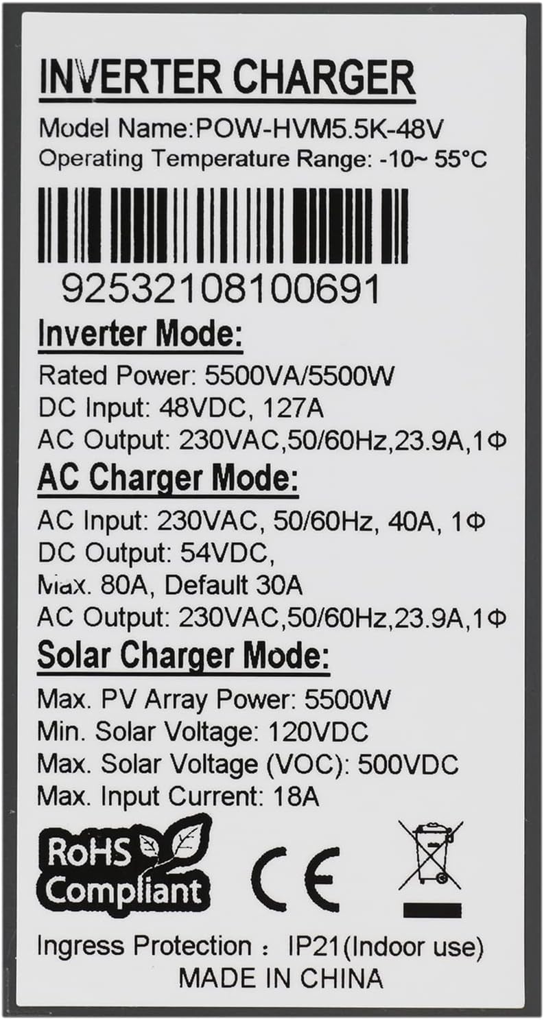
Figure 4.1: LCD Display and Control Panel. This image focuses on the inverter's user interface, showing the digital display with various indicators (e.g., input voltage, output voltage, battery status, charge status, fault indicators) and the array of buttons for navigation and setting adjustments.
4.3 Operating Modes
The inverter charger supports several operating modes:
- Inverter Mode: Converts DC power from batteries or solar panels into AC power for loads.
- AC Charger Mode: Charges batteries from an AC utility or generator source.
- Solar Charger Mode: Charges batteries directly from solar panels using MPPT technology.
- Hybrid Mode: Combines solar, battery, and AC power to efficiently supply loads and charge batteries.
5. Maintenance
- Regular Cleaning: Keep the inverter's ventilation openings clear of dust and debris to ensure proper airflow. Use a dry cloth for cleaning.
- Connection Inspection: Periodically check all wiring connections for tightness and signs of corrosion.
- Environmental Check: Ensure the installation environment remains within specified temperature and humidity ranges.
6. Troubleshooting
| Problem | Possible Cause | Solution |
|---|---|---|
| Inverter not turning on | No battery connection or low battery voltage; DC breaker off. | Check battery connections and voltage. Ensure DC breaker is on. |
| No AC output | Overload; AC output breaker tripped; Inverter fault. | Reduce load. Check AC output breaker. Consult fault codes on LCD. |
| Battery not charging from solar | PV input voltage too low/high; PV array disconnected; MPPT fault. | Check PV connections and voltage. Ensure sufficient sunlight. |
For issues not listed here or persistent problems, please contact Nairtech customer support.
7. Technical Specifications
| Parameter | Value |
|---|---|
| Model Number | POWHVM5.5K48vP |
| Rated Power | 5500W / 5500VA |
| Maximum Output Power | 6000W |
| Output Voltage Waveform | Pure Sine Wave |
| Output Voltage | 220 VAC / 230 VAC (Configurable) |
| Output Frequency | 50/60 Hz (Auto sensing) |
| DC Input Voltage | 48 VDC |
| Max. PV Array Power | 5500W |
| MPPT Range @ Operating Voltage | 120-450 VDC |
| Max. PV Array Open Circuit Voltage | 500 VDC |
| Max. Solar Charge Current | 100A |
| Max. AC Charge Current | 80A |
| Efficiency (Peak) | 93% |
| Dimensions (D x W x H) | 500 x 420 x 200 mm |
| Operating Temperature Range | -10°C to 55°C |
| Ingress Protection | IP21 (Indoor use) |
| Circuit Topology | Full Bridge |
Note: Specifications are subject to change without prior notice.
8. Warranty and Customer Support
Nairtech products are designed for reliability and performance. For warranty information, please refer to the warranty card included with your product or visit the official Nairtech website. For technical assistance, troubleshooting beyond this manual, or to report issues, please contact Nairtech customer support through their official channels.
When contacting support, please have your model number (POWHVM5.5K48vP) and serial number (if applicable, e.g., 92532108100691) ready.