
LDHJBNAC DECS-150 5NS1V1N1S
Automatic Voltage Regulator DECS-150 User Manual
Model: DECS-150 5NS1V1N1S | Brand: LDHJBNAC
1. Product Overview
The DECS-150 is a digital automatic voltage regulator designed for brushless AC synchronous generators or synchronous motor sets. It provides precise control over excitation power, ensuring stable and efficient operation. The unit features a pulse width modulated filter switch power module for excitation power delivery, capable of continuous supply under specified ambient conditions.
This model, DECS-150 5NS1V1N1S, is engineered for reliability and consistent performance in demanding environments.
Key Features
- Engine Voltage Regulator and Rectifier: A comprehensive solution for voltage regulation and rectification, designed for high quality and efficiency.
- High-Quality Capacitance: Ensures smooth and efficient operation with consistent parameter performance.
- Precise Resistance: Utilizes high-precision resistance for stable operation across a wide temperature range.
- Smooth Potentiometer: Allows for easy and durable adjustment of settings.
- Reliable Capacitors: Incorporates high-quality capacitors for consistent performance under various conditions.

Figure 1: Front view of the DECS-150 Automatic Voltage Regulator, highlighting its compact design and component layout.
2. Setup and Installation
Proper installation is crucial for the optimal performance and longevity of the DECS-150. Ensure all safety precautions are followed during installation.
2.1 Safety Precautions
- Disconnect all power sources before installation or maintenance.
- Ensure the installation environment is dry and free from excessive dust or corrosive gases.
- Only qualified personnel should perform installation and wiring.
- Verify all connections are secure and correct before applying power.
2.2 Mounting
Mount the DECS-150 in a location that allows for adequate ventilation and easy access for wiring and adjustments. Use appropriate fasteners to secure the unit firmly.
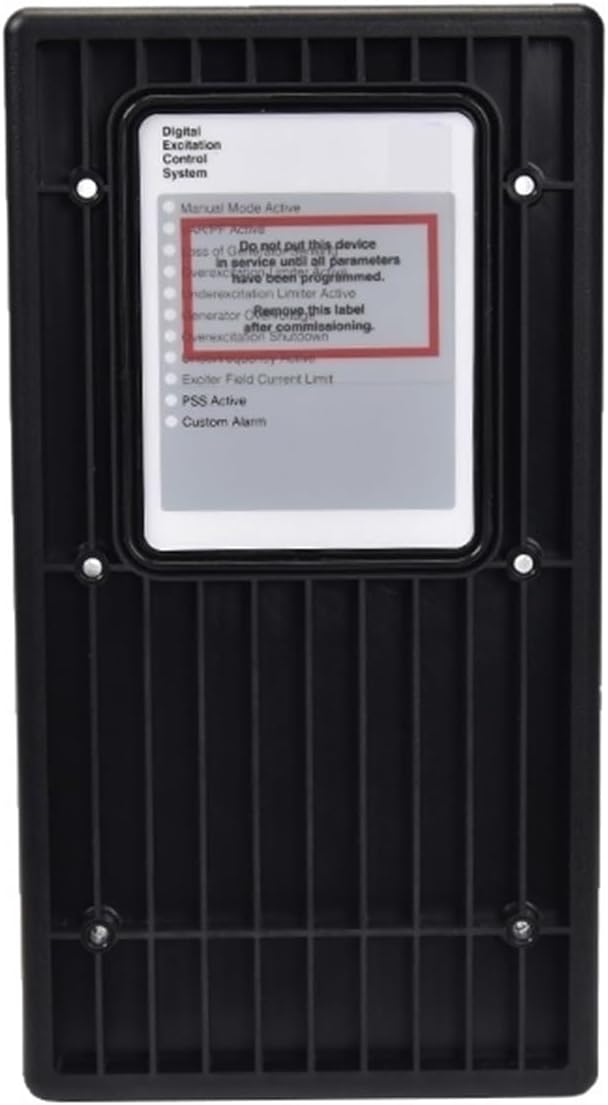
Figure 2: Back view of the DECS-150, illustrating the mounting points and the warning label regarding initial setup.
2.3 Wiring Connections
Refer to the wiring diagram provided with your generator or motor set for specific connection points. The DECS-150 typically requires connections for sensing voltage, excitation output, and power supply.
- Power Input: Connect the nominal voltage (63 Vdc or 125 Vdc) to the designated power input terminals.
- Sensing Input: Connect the voltage sensing lines from the generator/motor to the sensing input terminals.
- Excitation Output: Connect the excitation output terminals to the exciter field of the generator/motor.

Figure 3: Angled view of the DECS-150, providing a clearer perspective of the terminal blocks for wiring connections.
3. Operating Instructions
The DECS-150 is designed for straightforward operation once properly installed and configured.
3.1 Initial Power-Up
After completing all wiring, apply power to the system. The DECS-150 will perform a self-check. Observe any indicator lights or diagnostic messages.
3.2 Operating Modes
The DECS-150 supports both generator and motor operating modes. The operating mode can be changed via the unit's interface or associated control system. In motor mode, power factor and reactive power measurements will be inverted.

Figure 4: Top-down view of the DECS-150, illustrating the overall component layout and heat sinks for thermal management.
3.3 Adjusting Set Values
Adjustments to set values, such as voltage output, can be made through the integrated potentiometer or via connected control systems. Ensure adjustments are made incrementally and monitored for system stability.
4. Maintenance
The DECS-150 is designed for minimal maintenance. However, periodic checks can help ensure long-term reliability.
- Visual Inspection: Periodically inspect the unit for any signs of physical damage, loose connections, or excessive dust accumulation.
- Cleaning: If necessary, gently clean the unit with a soft, dry cloth. Do not use liquid cleaners or solvents. Ensure power is disconnected before cleaning.
- Connection Checks: Verify that all wiring connections remain tight and secure.
5. Troubleshooting
This section provides guidance for common issues. For complex problems, contact technical support.
| Problem | Possible Cause | Solution |
|---|---|---|
| No Output Voltage | No input power; Incorrect wiring; Internal fault. | Check power supply; Verify all wiring connections; Contact support if problem persists. |
| Unstable Voltage | Loose connections; Improper settings; Load fluctuations. | Tighten connections; Re-calibrate settings; Assess load conditions. |
| Overheating | Insufficient ventilation; Overload condition. | Ensure adequate airflow around the unit; Reduce load if possible. |

Figure 5: Side-by-side view of the DECS-150, illustrating both the component side and the protective casing side.
6. Specifications
| Parameter | Value |
|---|---|
| Model | DECS-150 5NS1V1N1S |
| Brand | LDHJBNAC |
| Power Input | Nominal 63 Vdc or 125 Vdc |
| Continuous Current (70°C ambient) | 7 Adc |
| Continuous Current (55°C ambient) | 10 Adc |
| Peak Current (70°C ambient) | 11 Adc |
| Peak Current (55°C ambient) | 14 Adc |
| Package Dimensions | 1.18 x 0.79 x 0.39 inches |
| Item Weight | 15.9 ounces |
| Manufacturer | LDHJBNAC |
7. Warranty and Support
For warranty information and technical support, please contact the manufacturer, LDHJBNAC, or your authorized distributor. Keep your purchase receipt and product model number handy for faster service.
Return Policy: This product typically has a 30-day refund/replacement policy from the date of purchase, subject to seller terms.
Related Documents - DECS-150 5NS1V1N1S
 |
Basler DECS-250 Digital Excitation Control System | Generator Control The Basler DECS-250 is a complete digital excitation control system offering precise voltage, var, and Power Factor regulation, generator protection, and optional power system stabilization. Learn about its features, specifications, and applications. |
Ask a question about this manual
Ask about setup, troubleshooting, compatibility, parts, safety, or missing instructions. Manuals+ will review the question and use this page’s manual context to help answer it.