
1. Introduction
This manual provides detailed instructions for the installation, operation, and maintenance of the HENGCMM Wind Solar Hybrid Charge Controller. This controller is designed for small off-grid installations, efficiently managing power from both wind turbines and solar panels to charge batteries.
The controller features intelligent MPPT boost control for wind turbine charging, stepless PWM fan discharge, and PWM overcurrent protection for solar panel charging. It supports dual power supply from battery and photovoltaic panels and offers multiple load output working modes. The internal circuit board is protected with a three-proof paint coating against dust, moisture, and static electricity.
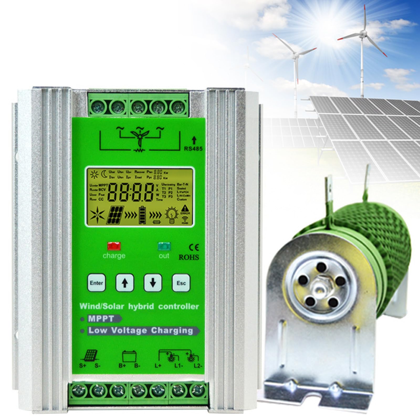
Image 1.1: Front view of the HENGCMM Wind Solar Hybrid Charge Controller.
2. Safety Information
Please read all safety instructions carefully before installation and operation to prevent injury or damage to the equipment. Keep this manual for future reference.
- Do not plug or unplug the power adapter with wet hands.
- Ensure correct wiring and polarity for all connections. Refer to the connection diagrams in this manual.
- The controller should be installed in a well-ventilated area, away from flammable materials and direct sunlight.
- Only qualified personnel should perform installation and maintenance.
- Ensure the system voltage matches the controller's rated voltage (12V/24V/48V).
- The controller is designed for specific battery types. Verify compatibility before connection.
3. Product Features
- Hybrid Charging: Automatically identifies and combines 12V, 24V, or 48V batteries for wind and solar power input.
- MPPT Technology: Wind turbine charging utilizes a boost MPPT control algorithm for efficient charging even at low wind speeds.
- PWM Charging: Solar panel charging uses PWM technology via series MOS tubes.
- Stepless Discharge: Features a stepless discharge function, including an external unloading resistor.
- LCD Display: Large LCD screen displays clear information and all parameters for easy monitoring and adjustment.
- Multiple Protections: Includes solar reverse connection protection, overcharge, undervoltage, overload protection, battery reverse connection, open circuit protection, and lightning protection.
- Adjustable Modes: Supports various load output working modes: pure light control, normally open, and light control + time control (four periods + morning light).
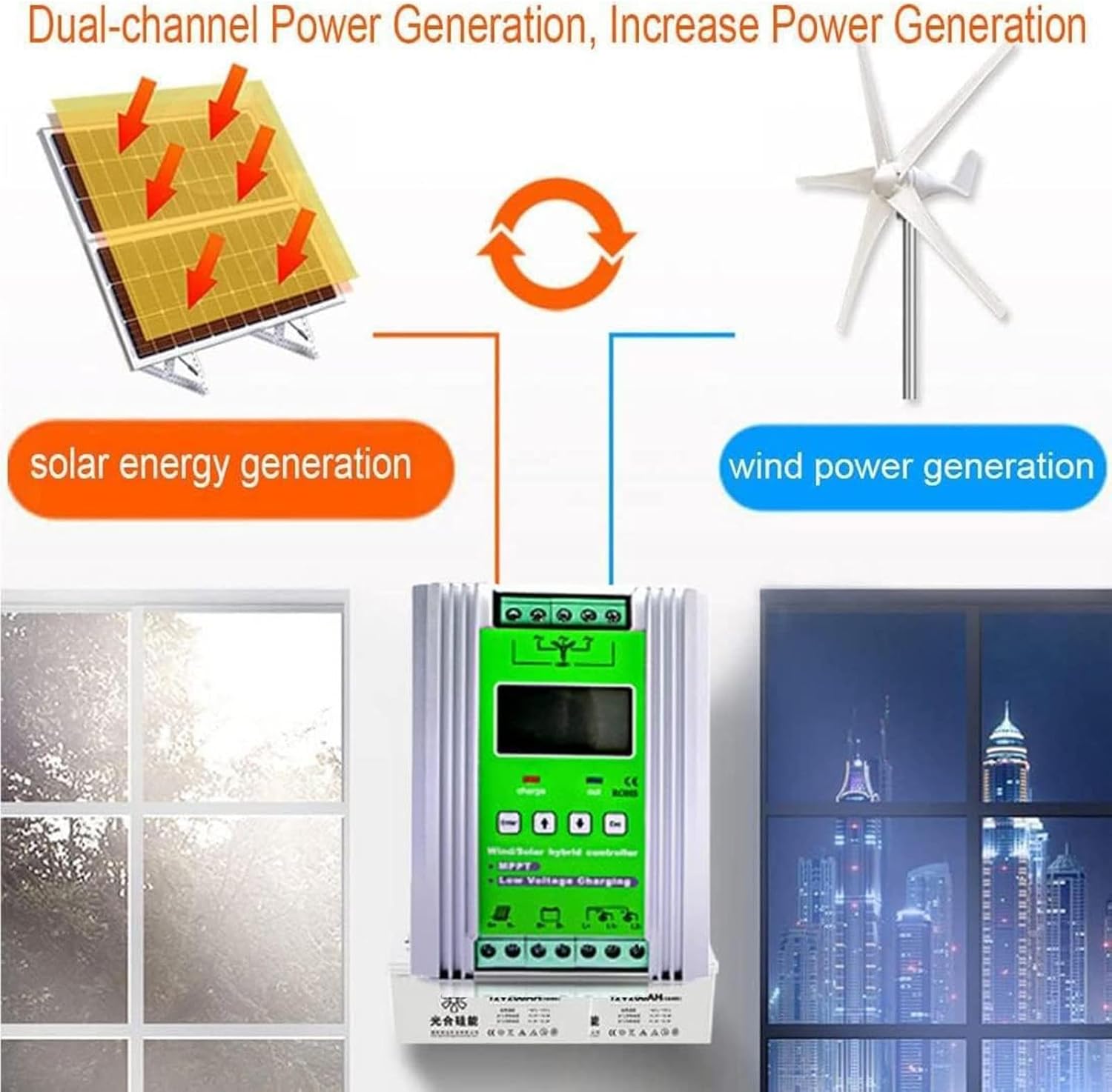
Image 3.1: Diagram illustrating dual-channel power generation from wind and solar sources.
4. Components and Interface
Familiarize yourself with the controller's components and interface before installation.
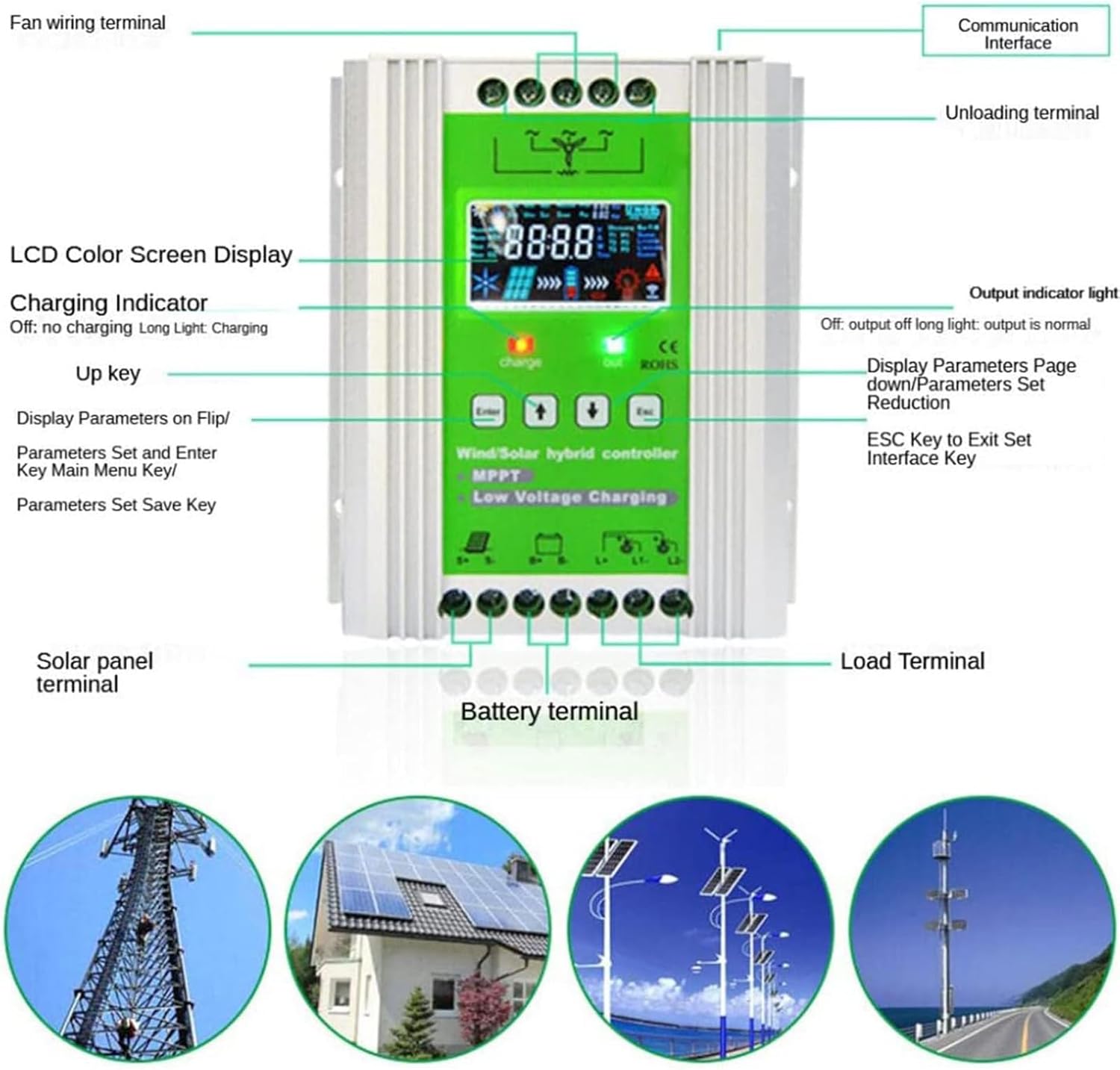
Image 4.1: Overview of the controller's front panel, LCD screen, and connection terminals.
- Fan Wiring Terminal: Connects to the wind turbine.
- Communication Interface: For data communication (e.g., RS485).
- Unloading Terminal: Connects to the external unloading resistor.
- LCD Color Screen Display: Shows system status and parameters.
- Charging Indicator: Indicates charging status (Off: no charging, Long Light: charging).
- Up Key: Used to navigate menus and increase parameter values.
- Enter Key: Used to select options, enter menus, and save settings.
- Down Key: Used to navigate menus and decrease parameter values.
- ESC Key: Used to exit the current interface or menu.
- Solar Panel Terminal: Connects to the solar photovoltaic array.
- Battery Terminal: Connects to the battery bank.
- Load Terminal: Connects to DC loads.

Image 4.2: Close-up of the LCD display showing various parameters and a side view of communication ports.
5. Setup and Installation
Follow these steps for proper installation of the hybrid charge controller.
- Mounting: Choose a suitable location for mounting the controller. It should be indoors, protected from direct sunlight, rain, and excessive dust. Ensure adequate ventilation around the unit for heat dissipation.
- Connect Battery: Connect the battery bank to the Battery Terminal (B+ and B-) on the controller. Ensure correct polarity. The controller will power on once the battery is connected.
- Connect Solar Panel: Connect the solar photovoltaic array to the Solar Panel Terminal (S+ and S-) on the controller. Ensure correct polarity.
- Connect Wind Turbine: Connect the wind turbine to the Fan Wiring Terminal (L1, L2, L3) on the controller.
- Connect Unloading Resistor: Connect the external unloading resistor to the Unloading Terminal on the controller. This is crucial for safe operation of the wind turbine.
- Connect DC Load (Optional): If using DC loads directly from the controller, connect them to the Load Terminal.
- Verify Connections: Double-check all connections for correct polarity and secure fastening before proceeding.

Image 5.1: Wiring diagram for connecting the wind turbine, PV array, battery, unloading resistor, and load to the controller.
6. Operating Instructions
The controller features an LCD display for monitoring and setting parameters. Use the Up, Down, Enter, and ESC keys to navigate.
6.1. LCD Display Parameters
The LCD displays real-time information such as:
- Voltage (Ubat, Ufan, Upv)
- Battery Power
- Current (Ifan, Ipv, Iload)
- Power (Pfan, Ppv, Pload)
- Load Mode
- Temperature
- Battery Type (e.g., Gel, Sealed, LiFePO4, LiNiCoMn, Custom)
- Protection Status (e.g., Undervoltage, Overcurrent)
6.2. Setting Operating Modes
The controller supports multiple load output working modes. Access the settings menu using the Enter key and navigate with the Up/Down keys to select your desired mode:
- Pure Light Control Mode: Load output is controlled solely by ambient light levels.
- Normally Open Mode: Load output is continuously on.
- Light Control + Time Control Mode: Load output is activated by light levels and then operates for a set duration (four periods) or until morning light.
Refer to the on-screen prompts for detailed parameter adjustments within each mode.
7. Specifications
| Parameter | Value |
|---|---|
| System Rated Voltage | 12V/24V/48V (Auto-sensing) |
| No-load Current (DC) | ≤0.05A |
| Controller Power Supply Mode | Battery or Photovoltaic Panel |
| Wind Control Method | MPPT Boost, PWM Unloading, PWM Overcurrent |
| Solar Control Method | PWM Charging |
| Load Output Modes | Pure Light Control, Normally Open, Light Control + Time Control |
| Display Mode | LCD Display |
| Heat Dissipation Method | Aluminum Profile Heat Dissipation and Self-cooling |
| Working Temperature Range | -20°C to +55°C |
| Working Humidity Range | 35% to 85% RH (no condensation) |
| Dimensions (Approximate) | 16.5 inches (Length) x 5.55 inches (Width) x 2.6 inches (Height) |
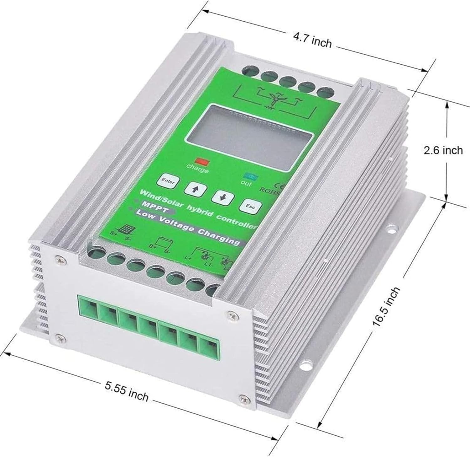
Image 7.1: Diagram showing the approximate dimensions of the hybrid charge controller.
8. Maintenance
Regular maintenance ensures optimal performance and longevity of your charge controller.
- Cleaning: Periodically clean the exterior of the controller with a dry, soft cloth. Ensure ventilation openings are free from dust and debris.
- Connection Check: Annually inspect all wiring connections for tightness and corrosion. Re-tighten if necessary.
- Environmental Check: Ensure the installation environment remains within the specified temperature and humidity ranges.
- Firmware Updates: Check the manufacturer's website for any available firmware updates.
9. Troubleshooting
This section provides guidance for common issues. For complex problems, contact customer support.
9.1. Common Issues and Solutions
- Controller Not Powering On:
- Check battery connections and ensure correct polarity.
- Verify battery voltage is within the operating range.
- No Charging from Solar Panels:
- Check solar panel connections and polarity.
- Ensure sufficient sunlight is reaching the panels.
- Verify solar panel voltage is within the controller's input range.
- No Charging from Wind Turbine:
- Check wind turbine connections.
- Ensure adequate wind speed for turbine operation.
- Verify the unloading resistor is correctly connected.
- Load Not Working:
- Check load connections and ensure correct polarity.
- Verify the selected load output mode is active.
- Check for overload conditions or short circuits.
10. Warranty and Support
For warranty information or technical support, please contact HENGCMM customer service. Details regarding warranty periods and terms are typically provided with your purchase documentation.
If you have any questions or require assistance, please feel free to contact us through the retailer or the official HENGCMM support channels.
Note: The manufacturer reserves the right to make changes to the product and specifications without prior notice.
11. Application Scenarios
The HENGCMM Wind Solar Hybrid Charge Controller is versatile and suitable for various off-grid applications, including:
- Residential wind and solar hybrid power generation systems.
- Remote mountainous area photovoltaic power generation.
- Grassland pasture power consumption.
- Street lighting systems.
- Marine applications (ships).
- Outdoor monitoring stations.

Image 11.1: Examples of typical installations and application environments for the hybrid charge controller.