
1. Introduction
This manual provides detailed instructions for the installation, operation, and maintenance of the Intellinet 48-Port L3 Managed Gigabit PoE+ Switch, Model 562041. This device is designed for enterprise networks requiring efficient and scalable routing solutions with high-powered Power over Ethernet (PoE) capabilities.
2. Safety Information
Observe the following safety precautions to prevent damage to the device and injury to personnel:
- Ensure proper grounding of the device.
- Do not expose the switch to water or excessive humidity.
- Operate the device within the specified temperature and humidity ranges.
- Use only the power cable provided or a compatible replacement.
- Do not open the switch casing; refer servicing to qualified personnel.
- Ensure adequate ventilation around the switch to prevent overheating.
3. Package Contents
Verify that all items are present in the package:
- Intellinet 48-Port L3 Managed Gigabit PoE+ Switch (Model 562041)
- Power cable
- 19" rackmount brackets
- Rubber feet
- Instructions (this manual)
4. Product Overview
The Intellinet 562041 is a robust Layer 3 managed switch featuring 48 Gigabit PoE+ ports and six 10G SFP+ uplink slots. It supports a total power budget of 850 watts for PoE devices.
4.1 Front Panel
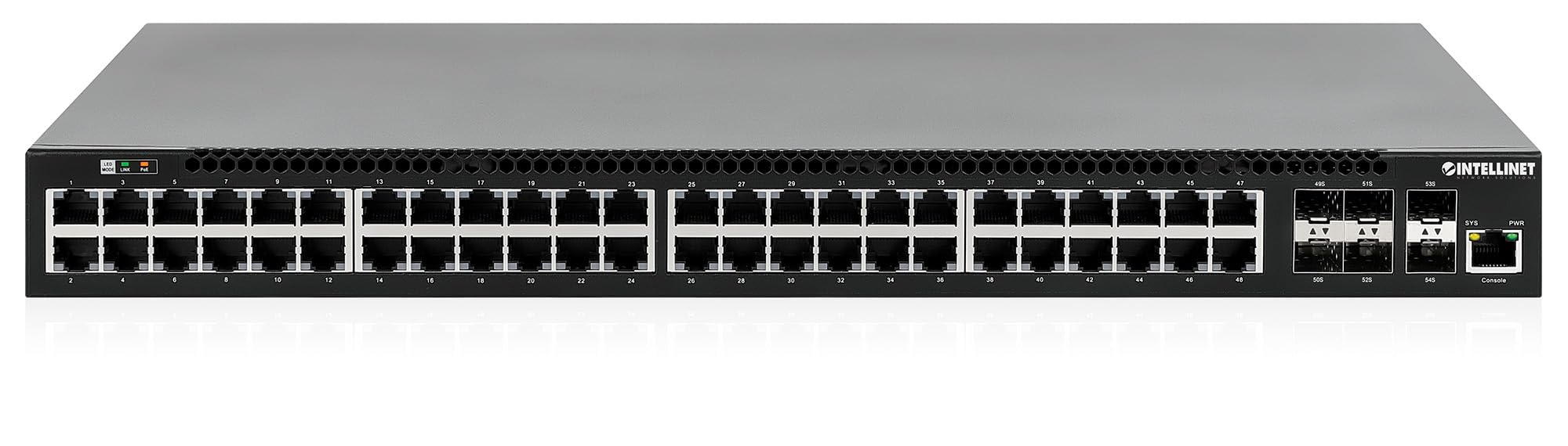
The front panel includes:
- 48 x 10/100/1000 Mbps RJ45 Ports: These ports support Power over Ethernet Plus (PoE+) for connecting compatible devices.
- 6 x 10 Gigabit SFP+ Slots: For high-speed uplink connections to other network devices.
- LED Indicators: Provide status information for power, system, link activity, and PoE status.
- Console Port: For local management and configuration.


4.2 Rear Panel

The rear panel typically includes the AC power input and cooling fans for heat dissipation.

5. Setup
5.1 Physical Installation
The switch can be installed in a standard 19-inch equipment rack or placed on a desktop.
- Rackmount Installation: Attach the provided rackmount brackets to the sides of the switch using the included screws. Secure the switch into a standard 19-inch rack.
- Desktop Installation: Attach the provided rubber feet to the bottom of the switch to prevent scratching and ensure stability. Place the switch on a flat, stable surface.
5.2 Power Connection
Connect the provided power cable to the AC power input on the rear panel of the switch and then to a grounded electrical outlet. Ensure the power switch is in the OFF position before connecting the power cable.
5.3 Network Connections
- PoE Devices: Connect PoE-compatible devices (e.g., IP cameras, VoIP phones, wireless access points) to any of the 48 Gigabit RJ45 ports. The switch will automatically detect and provide power to these devices.
- Uplink Connections: Insert compatible SFP+ transceivers into the 10 Gigabit SFP+ slots and connect them to your core network or other high-speed devices using appropriate fiber optic cables.
- Console Connection: For initial configuration or direct management, connect a console cable from your computer to the console port on the switch.
5.4 Initial Configuration
Refer to the separate software configuration guide for detailed instructions on accessing the switch's management interface (web-based GUI or command-line interface via console port) and performing initial setup, including IP address assignment, user accounts, and basic network settings.
6. Operating Instructions
6.1 Layer 3 Routing
This switch offers dynamic Layer 3 IP routing capabilities, including OSPF (Open Shortest Path First), RIP (Routing Information Protocol), and VRRP (Virtual Router Redundancy Protocol). These protocols enable efficient and scalable routing within complex network environments.

6.2 Power over Ethernet (PoE+)
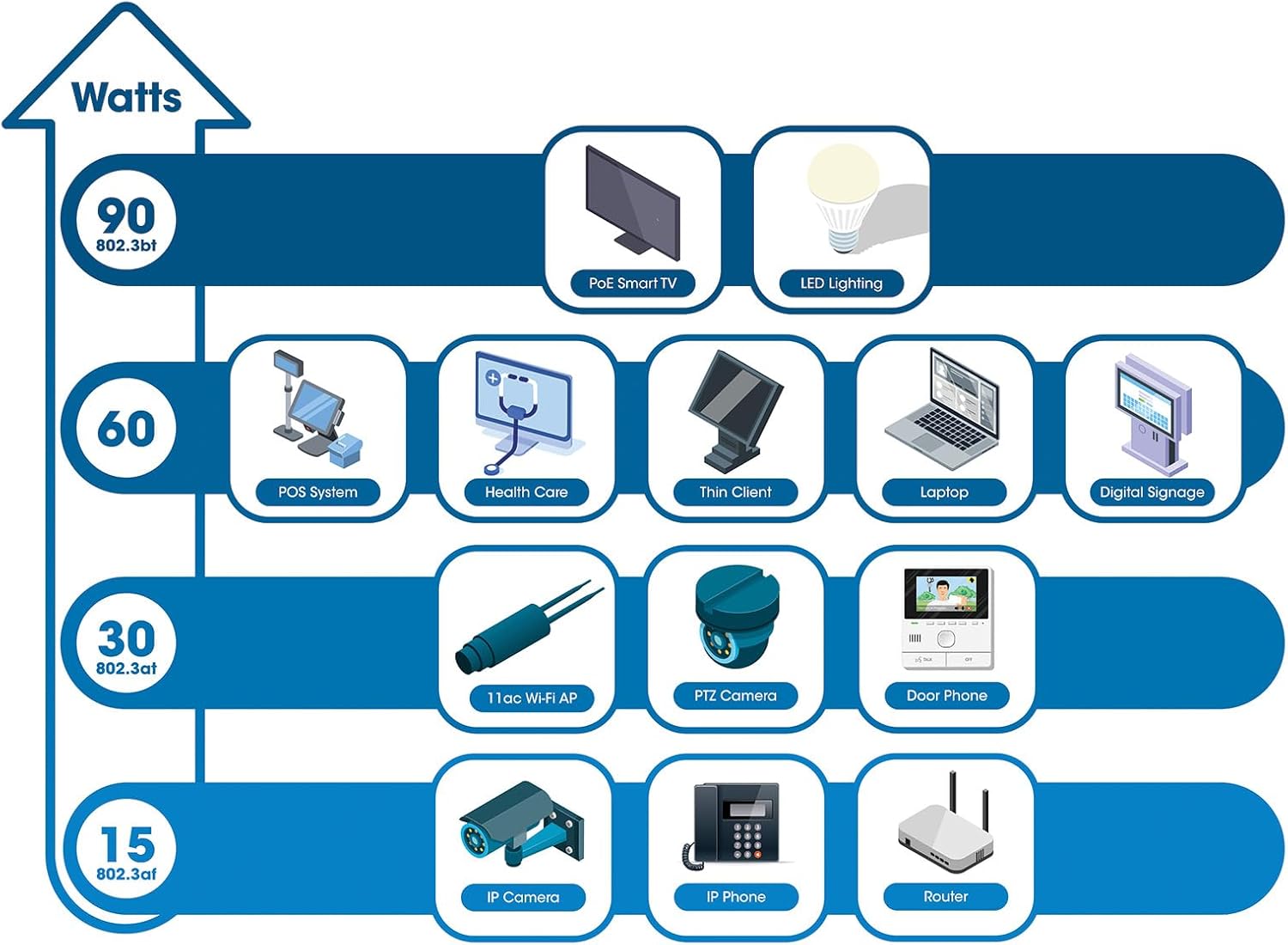
The switch provides up to 30 watts of power per port across its 48 PoE+ ports, with a total power budget of 850 watts. This allows for seamless integration of various PoE devices without the need for separate power adapters.
6.3 PoE Scheduling
The switch supports PoE scheduling, allowing administrators to define specific times for powering on, powering off, or rebooting connected PoE devices. This feature can optimize power consumption and enhance network security.


6.4 Self-Healing Functionality (PDM)
The Powered Device Monitor (PDM) feature enables the switch to proactively monitor the status of connected PoE devices. If a device becomes unresponsive, the PDM can automatically restart the PoE port to restore functionality, minimizing downtime and maintaining network integrity.
6.5 Cloud Management
The switch supports cloud management capabilities, allowing for remote configuration, monitoring, and troubleshooting of the device from a centralized platform. Refer to the cloud management documentation for setup and usage details.
7. Maintenance
7.1 Firmware Updates
Regularly check the Intellinet Network Solutions website for the latest firmware updates. Applying firmware updates can improve performance, add new features, and address security vulnerabilities. Follow the instructions provided with the firmware update package carefully.
7.2 Cleaning
To clean the switch, power it off and disconnect all cables. Use a soft, dry cloth to wipe the exterior. Do not use liquid or aerosol cleaners. Ensure ventilation openings are free from dust and debris.
7.3 Environmental Considerations
Ensure the switch operates within its specified temperature and humidity ranges. Avoid placing the switch in direct sunlight, near heat sources, or in areas with high dust accumulation.
8. Troubleshooting
This section addresses common issues you might encounter with the switch.
8.1 No Power
- Verify the power cable is securely connected to both the switch and a working electrical outlet.
- Ensure the power switch on the rear panel is in the ON position.
- Check the power outlet with another device to confirm it is functional.
8.2 No Link on a Port
- Check the Ethernet cable connection at both ends. Ensure it is securely plugged in.
- Verify the cable is not damaged. Try a different cable.
- Ensure the connected device is powered on and functioning correctly.
- Check the port status in the switch's management interface.
8.3 PoE Device Not Receiving Power
- Confirm the connected device is a PoE-compatible device.
- Check the PoE status LED for the specific port.
- Verify the total PoE power budget (850W) is not exceeded by all connected devices.
- Utilize the Powered Device Monitor (PDM) feature to automatically restart the port if the device is unresponsive.
- Check PoE settings in the switch's management interface.
9. Specifications
| Feature | Specification |
|---|---|
| Model Number | 562041 |
| Brand | INTELLINET NETWORK SOLUTIONS |
| Number of Ports | 54 (48 x Gigabit PoE+, 6 x 10G SFP+) |
| Interface Type | PoE, SFP |
| Maximum Power (PoE Budget) | 850 Watts |
| Data Transfer Rate | 10 Gigabits Per Second (SFP+ uplinks) |
| Item Weight | 6.2 Kilograms (13.64 pounds) |
| Product Dimensions (L x W x H) | 13.78 x 17.32 x 1.73 inches |
| Upper Temperature Rating | 104 Degrees Fahrenheit (40°C) |
| Lower Temperature Rating | 32 Degrees Fahrenheit (0°C) |
| Compatible Devices | Desktop, Router, PoE devices (IP cameras, VoIP phones, WAPs) |
| Included Components | 19" rackmount brackets, Instructions, Rubber feet, power cable |
| UPC | 766623562041 |
10. Warranty and Support
10.1 Warranty Information
This Intellinet Network Solutions product is covered by a 3-Year Manufacturer's Warranty. Please retain your proof of purchase for warranty claims. The warranty covers defects in materials and workmanship under normal use.
10.2 Technical Support
For technical assistance, product documentation, or to register your product, please visit the official Intellinet Network Solutions website or contact their customer support. Contact information can typically be found on the manufacturer's website or in the product packaging.


