Introduction
This manual provides essential instructions for the safe and efficient operation of your Abestop AT6301 Lab Power Supply. The AT6301 is a high-precision DC power supply designed for laboratory, educational, and DIY applications, offering a stable and reliable power source. It features a 2.8-inch TFT LCD, 4-digit display, and multiple protection functions to ensure safe usage.

Figure 1: Abestop AT6301 Lab Power Supply in operation, displaying voltage and current, alongside a clamp meter for external measurement. This image highlights the device's precise output capabilities.
Key Features:
- Output Range: 0-60V / 0-10A, with a maximum output power of 300W.
- High Resolution: 10mV / 1mA for precise adjustments.
- Display: 2.8-inch TFT LCD with 4-digit display for clear readings.
- USB Charging Port: 5V/1A output for convenient device charging.
- Protection Functions: Includes Over Voltage Protection (OVP) and Over Current Protection (OCP) for enhanced safety.
- Memory Functions: 4 groups of data memory (M1-M4) for quick recall of settings.
- Waveform Output: Supports waveform output with 10 editable points.
- Cooling: Intelligent temperature-controlled fan ensures stable long-term operation.
- Connectivity: USB communication interface with SCPI support.
- Compact Design: Lightweight and portable, suitable for various environments.
Safety Precautions
Always observe the following safety guidelines to prevent injury or damage to the device:
- Ensure the power cord is properly grounded to avoid electric shock.
- Do not operate the device in wet or damp conditions.
- Do not open the casing or attempt to repair the unit. Refer servicing to qualified personnel.
- Verify input voltage matches local power supply specifications.
- Avoid short-circuiting the output terminals.
- Ensure proper ventilation to prevent overheating.

Figure 2: The Abestop AT6301 features comprehensive protection mechanisms, including overvoltage, overcurrent, short-circuit, overtemperature, and overload protection, ensuring safe operation.
Setup
1. Unpacking and Inspection:
Carefully remove the power supply from its packaging. Inspect the unit for any signs of physical damage. Ensure all accessories, including the power cord and test leads, are present.
2. Connecting Power:
- Connect the provided power cord to the power input socket on the rear panel of the device.
- Plug the other end of the power cord into a grounded AC power outlet.
- Ensure the power switch on the rear panel is in the OFF position before connecting to the mains.
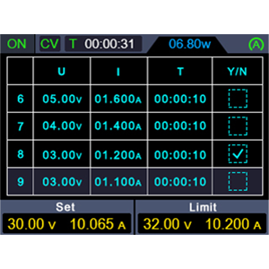
Figure 3: Rear panel connections of the AT6301, including the power input, fuse, power switch, and USB communication port. Note the intelligent temperature control fan for efficient cooling.
3. Initial Power On:
Flip the power switch on the rear panel to the ON position. The LCD screen on the front panel should illuminate, displaying the startup sequence and default settings.
Operating Instructions
1. Front Panel Overview:

Figure 4: Detailed view of the AT6301 front panel, indicating the functions of each control and display element for easy operation.
2. Setting Voltage and Current:
- Press the V button to select voltage adjustment. Use the adjustment knob to set the desired voltage.
- Press the I button to select current adjustment. Use the adjustment knob to set the desired current limit.
- The display will show the set values (Set) and the actual output values.
3. Output Control:
Press the On/Off button to enable or disable the output. The button will illuminate when the output is active. Long press the On/Off button to activate the automatic output function.
4. Over Voltage Protection (OVP) and Over Current Protection (OCP):
To set OVP or OCP limits, press the respective OVP or OCP button and use the adjustment knob to set the maximum allowable voltage or current. These features protect your connected device from damage.
5. Memory Functions (M1-M4):
The AT6301 allows you to save and recall up to 4 groups of frequently used voltage and current settings.
- To save a setting: Adjust voltage and current to the desired values. Long press the Memory button, then select a memory location (M1-M4) using the adjustment knob and confirm.
- To recall a setting: Short press the Memory button, then select the desired memory location (M1-M4) and confirm.
6. Waveform Output List:
The device supports a waveform output list with 10 editable points. Each point allows modification of output voltage, current, and waveform duration.
- Long press the shortcut output button (often labeled with a list icon or similar) to enter the waveform editing interface.
- Use the adjustment knob and navigation buttons to modify the parameters for each of the 10 points.
- Confirm your settings to activate the waveform output.

Figure 5: The AT6301 displaying a waveform output, illustrating its capability for programmable output sequences.
7. USB Charging Port:
The front USB port provides 5V/1A output, suitable for charging mobile devices or powering low-current USB accessories.

Figure 6: The integrated USB port allows for convenient charging of external devices.
Maintenance
1. Cleaning:
To maintain the performance and appearance of your power supply, regularly clean the exterior with a soft, dry cloth. Do not use abrasive cleaners or solvents. Ensure the device is powered off and unplugged before cleaning.
2. Ventilation:
Ensure that the ventilation openings on the sides and rear of the unit are clear of obstructions to allow for proper airflow. The intelligent temperature-controlled fan requires unobstructed space to operate effectively.

Figure 7: The intelligent cooling fan actively dissipates heat, crucial for maintaining optimal performance and longevity.
3. Fuse Replacement:
If the power supply fails to turn on, check the fuse located on the rear panel near the power input.
- Disconnect the power cord from the mains supply.
- Using a small flat-head screwdriver, gently pry open the fuse holder.
- Remove the old fuse and replace it with a new fuse of the same type and rating (e.g., 5A).
- Close the fuse holder securely.
Troubleshooting
| Problem | Possible Cause | Solution |
|---|---|---|
| No power / Unit does not turn on |
|
|
| No output voltage/current |
|
|
| Unstable output readings |
|
|
| USB port not charging |
|
|
Specifications
| Parameter | Value |
|---|---|
| Model Number | AT6301 |
| Brand | Abestop |
| Output Voltage | 0-60 Volts |
| Output Current | 0-10 Amperes |
| Output Power | 300 Watts |
| USB Port Output | 5V/1A |
| Resolution | 10mV / 1mA |
| Display | 2.8-inch TFT LCD, 4-digit |
| Operating Temperature | 0-40 ℃ |
| Memory Groups | 4 groups |
| Communication Interface | USB (SCPI support) |
| Dimensions (L x W x H) | 14 x 23 x 9 centimeters (approx. 5.5 x 9.1 x 3.5 inches) |
| Item Weight | 1.5 Kilograms (approx. 3.3 lbs) |
| Color | Black |
| Country of Origin | China |
| Safety Compliance | CE |
Warranty Information
Abestop products are manufactured to high-quality standards. This product comes with a standard manufacturer's warranty against defects in materials and workmanship. Please refer to the warranty card included with your product or contact customer support for specific warranty terms and conditions. Keep your purchase receipt as proof of purchase for warranty claims.
Customer Support
For technical assistance, troubleshooting, or any questions regarding your Abestop AT6301 Lab Power Supply, please contact Abestop customer support.
- Online Support: Visit the official Abestop website for FAQs, product documentation, and contact forms.
- Email Support: Refer to your product packaging or the official website for the customer support email address.
- Phone Support: Contact numbers may be available on the official Abestop website for your region.
When contacting support, please have your product model number (AT6301) and purchase information readily available.