
MiOYOOW mini shooting game kit
MiOYOOW Electric Magnetic Transmitter Soldering Practice Kit: Instruction Manual
Model: mini shooting game kit
1. Introduction
This instruction manual provides comprehensive guidance for the assembly, operation, and maintenance of the MiOYOOW Electric Magnetic Transmitter Soldering Practice Kit. This kit is designed as a STEM educational project, allowing users to build a mini shooting game based on electromagnetic principles. It offers an opportunity to learn about electronic components and soldering techniques.

This image displays the fully assembled MiOYOOW Electric Magnetic Transmitter Soldering Practice Kit, featuring a clear acrylic casing, visible circuit board, coil, launch tube, and several small metal projectiles.
2. Safety Warnings
Please read and understand all safety warnings before beginning assembly or operation.
- High Voltage: The finished project operates under high voltage. Although the energy is small and the insulating plastic shell provides safety, avoid touching metal parts when the device is energized.
- Capacitor Discharge: Always discharge the energy storage capacitor before performing any troubleshooting or maintenance. Refer to the user manual for detailed discharge procedures.
- Adult Supervision: This kit is recommended for individuals aged 15 years and older. Users under the age of 14 must be supervised by an adult during both assembly and operation.
- Proper Tools: Use appropriate soldering tools and safety equipment, such as safety glasses, during assembly.
3. Package Contents
Verify that all components listed below are present in your package before starting assembly. If any parts are missing or damaged, please contact customer support.

This image shows all individual components of the kit laid out, including acrylic panels for the casing, resistors, diodes, capacitors, a battery holder, a coil, a switch, a push button, screws, wires, and the main circuit boards.
Included Components:
- Acrylic Casing Panels
- Main Circuit Boards (PCB)
- Electromagnetic Coil
- Launch Tube
- Resistors (various values)
- Capacitors
- Diodes
- Transistors
- Power Switch
- Launch Button (Red)
- LED Indicator Lights (Green, Blue, Red)
- Battery Holder (for 2x AA batteries, batteries not included)
- Connecting Wires
- Screws and Standoffs
- Small Cylindrical Metal Rods (Projectiles)
4. Assembly Instructions
The assembly process involves connecting circuits and mounting components. While some soldering is required, the design aims for a manageable build. A detailed PDF installation document is available by scanning the QR code provided in the paper user manual included with your kit.
General Assembly Steps:
- Prepare Components: Organize all electronic components and acrylic panels.
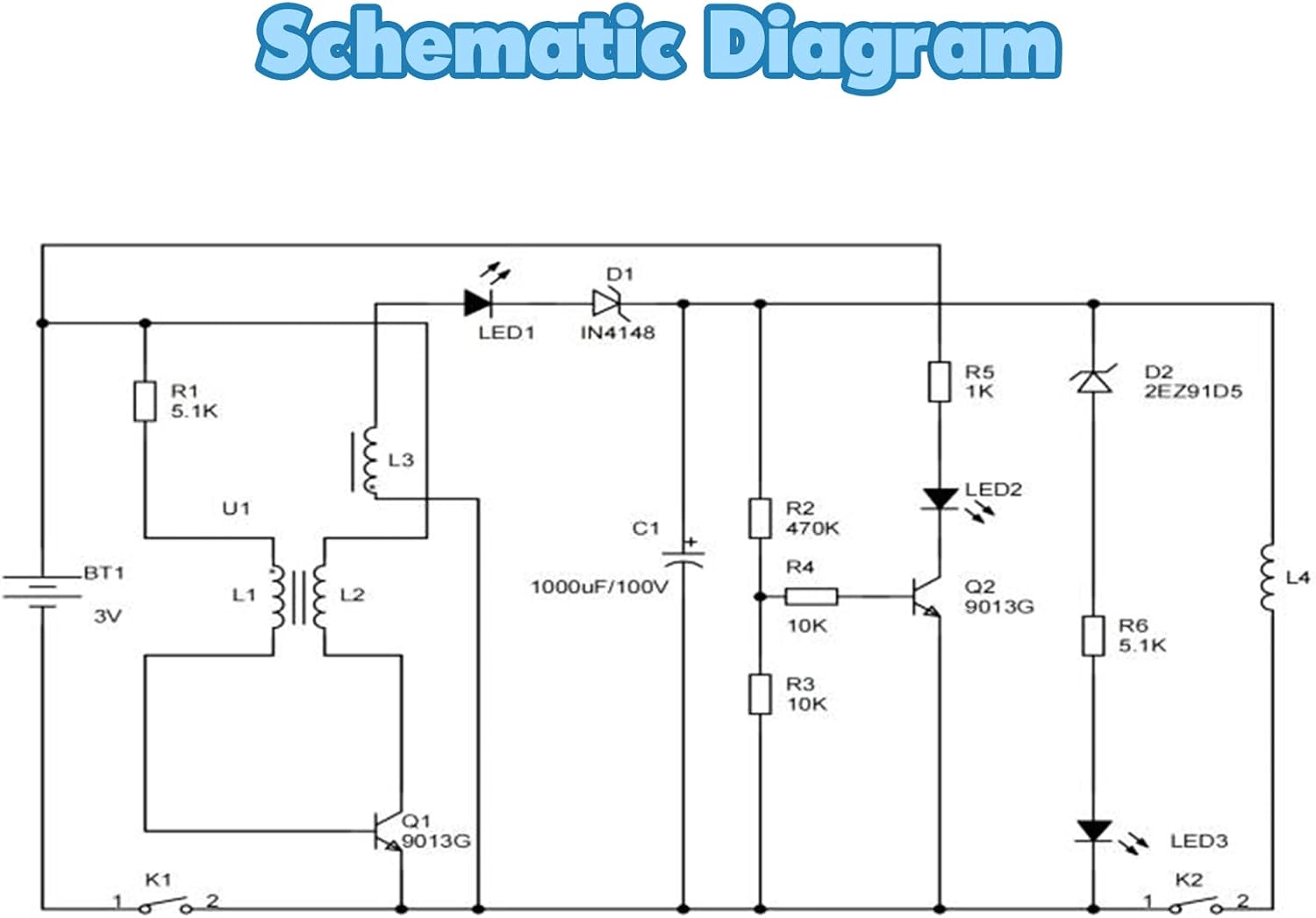
- Solder Components: Carefully solder the resistors, capacitors, diodes, transistors, and other small electronic parts onto the main circuit boards according to the schematic diagram and PCB markings.
- Connect Wires: Connect the power switch, launch button, coil, and battery holder to the circuit boards using the provided wires. Ensure correct polarity for all connections.
- Assemble Casing: Mount the assembled circuit boards and components within the clear acrylic casing using the screws and standoffs. Ensure the power switch and launch button are accessible.
- Install Coil and Tube: Securely attach the electromagnetic coil and the launch tube to their designated positions on the top board.
- Insert Batteries: Install 2x AA batteries (not included) into the battery compartment located at the bottom of the unit. The bottom battery compartment design allows for easy battery replacement without opening the main casing.

This diagram highlights and labels the main parts of the assembled kit, including the Power Switch, Launch Button, Indicator Light, Coil & Pipe, and Battery Case, providing a clear overview of its functional elements.
5. Operating Instructions
Follow these steps to operate your assembled Electric Magnetic Transmitter Kit:
- Power On: Toggle the power switch to the ON position. The green LED indicator light will illuminate, signaling that the circuit has started charging the capacitor.
- Wait for Charge: Allow 10-30 seconds for the capacitor to fully charge. The blue LED indicator light will illuminate once charging is complete.
- Load Projectile: Insert a cylindrical metal rod into the rear end of the plastic launch tube. Ensure the tail of the rod is flush with the tail of the tube.
- Launch: Press the red launch button. The electromagnetic field will accelerate the metal rod, causing it to launch from the tube.

A visual guide showing the operational steps: 1) Toggling the power switch, 2) Observing the blue diode light up and inserting the metal rod, and 3) Pressing the red launch button to fire the projectile.
6. Maintenance
To ensure the longevity and proper functioning of your kit, observe the following maintenance guidelines:
- Keep Dry: Protect the kit from moisture and liquids, as these can damage electronic components.
- Clean Gently: Use a soft, dry cloth to clean the acrylic casing. Avoid abrasive cleaners or solvents.
- Battery Care: Remove batteries if the kit will not be used for an extended period to prevent leakage.
- Storage: Store the kit in a cool, dry place away from direct sunlight and extreme temperatures.
7. Troubleshooting
If you encounter issues with your kit, refer to the following common problems and solutions:
- Kit Does Not Power On:
- Check if batteries are correctly inserted and have sufficient charge.
- Ensure the power switch is fully in the ON position.
- Verify all power connections are secure and correctly soldered.
- Green LED On, Blue LED Does Not Light Up (Capacitor Not Charging):
- Confirm all components related to the charging circuit (resistors, diodes, capacitor) are correctly installed and soldered.
- Ensure the capacitor is not damaged or installed with incorrect polarity.
- Allow sufficient time (up to 30 seconds) for charging.
- Projectile Does Not Launch or Launches Weakly:
- Ensure the blue LED is lit, indicating a full charge before attempting to launch.
- Verify the metal rod is inserted correctly and its tail is flush with the tube's end.
- Check the coil connections and ensure it is securely mounted.
- Inspect the launch button for proper function and secure connections.
- Ensure the projectile is not obstructed within the tube.
- Projectile Launches Backwards:
- This can occur if the projectile is not positioned correctly relative to the coil. Ensure the launch tube is pushed in sufficiently so that the projectile is positioned within the optimal magnetic field of the copper coil for forward propulsion.
Always discharge the energy storage capacitor before attempting any internal inspection or repair.
8. Specifications
| Feature | Detail |
|---|---|
| Manufacturer | MiOYOOW |
| Item Model Number | mini shooting game kit |
| Item Weight | 7.6 ounces |
| Package Dimensions | 4.84 x 3.43 x 2.99 inches |
| Material | Copper (for coil), Acrylic (for casing), various electronic components |
| Power Source | Battery Powered (2x AA batteries, not included) |
| Display Style | LED (indicator lights) |
| Batteries Required? | Yes |
| Date First Available | April 24, 2024 |
An image illustrating the physical dimensions of the assembled kit, showing its length (3.7 inches), width (3.42 inches), and height (1.87 inches, with the coil extending to 1.41 inches above the base).
9. Warranty and Support
For any questions, technical assistance, or issues regarding missing or defective parts, please contact the seller directly through the platform where the product was purchased. Provide your order details and a clear description of the issue for prompt support.
Ask a question about this manual
Ask about setup, troubleshooting, compatibility, parts, safety, or missing instructions. Manuals+ will review the question and use this page’s manual context to help answer it.