Irfora PN107
Irfora PN107 Digital Clamp Meter
User Manual
1. Introduction
Thank you for choosing the Irfora PN107 Digital Clamp Meter. This versatile and easy-to-use instrument is designed for accurate measurement of electrical parameters. It is ideal for electricians, DIY enthusiasts, and professionals requiring reliable measurements of AC/DC current, AC voltage, resistance, capacitance, and diode testing.
Please read this manual thoroughly before operation to ensure safe and proper use of the device.

Figure 1: Irfora PN107 Digital Clamp Meter (Black model)
This image shows the main view of the Irfora PN107 Digital Clamp Meter, highlighting its compact design and clear display. The clamp jaw is visible at the top, and the rotary dial for function selection is centrally located.
2. Safety Information
WARNING: To avoid possible electric shock or personal injury, and to avoid possible damage to the meter or to the equipment under test, follow these safety rules:
- Always ensure the meter is in the correct function mode and range before making measurements.
- Do not use the meter if it appears damaged or if the test leads are damaged.
- Do not apply more than the rated voltage, as marked on the meter, between the terminals or between any terminal and earth ground. This meter is rated CAT II 600V.
- Use extreme caution when working with voltages above 60V DC or 30V AC RMS. Such voltages pose a shock hazard.
- Keep your fingers behind the finger guards on the test leads during measurement.
- Remove the test leads from the circuit before changing functions.
- Do not operate the meter around explosive gas, vapor, or dust.
- Always disconnect power to the circuit and discharge all high-voltage capacitors before testing resistance, continuity, diodes, or capacitance.
- Replace the battery as soon as the low battery indicator appears to avoid incorrect readings.
3. Product Overview
3.1 Components
Familiarize yourself with the various parts of your PN107 Digital Clamp Meter:

Figure 2: Labeled Components of the PN107 Clamp Meter
This diagram provides a detailed breakdown of the PN107 Clamp Meter's components, including the pliers (clamp jaw), flashlight, AC current measurement area, wrench, capacitor, resistance, indicator light, function switch key, LCD screen, black and red watch pen jacks, turntable, diode/on-off buzzer, AC/DC voltage, NCV induction, Data Hold/Backlit bright screen, and NCV sensor.
- Pliers (Clamp Jaw): Used for non-contact AC current measurement.
- Flashlight: Illuminates the measurement area.
- Function Switch Key (FUN): Cycles through sub-functions within a rotary dial setting.
- Rotary Dial: Selects the main measurement function (e.g., AC Current, Voltage, Resistance).
- LCD Screen: Displays measurement readings and indicators.
- Input Jacks (COM, VΩ): For connecting test leads for voltage, resistance, capacitance, and diode measurements.
- NCV Sensor: Detects non-contact AC voltage.
- Data Hold/Backlight Button (H/*): Toggles data hold and screen backlight.
- Power Button: Turns the device on/off.
3.2 Key Features
- 600A High Current Measure: Capable of measuring up to 600A AC current, suitable for various wire measurements.
- AC Current Measure: Non-contact measurement of AC current using the clamp head.
- Clamp Mouth Non-contact Measure: 25mm caliber clamp meter for non-contact AC current measurement.
- NCV Contactless Induced: When AC voltage is detected, the screen will display "----", the LED red light will flash, and an alarm will sound.
- Backlit Bright Screen: High definition display for clear visibility in dark environments.
- Automatic Shutdown: The meter will automatically shut down if not used within 15 minutes to conserve battery life.
- Flashlight: Integrated flashlight for illuminating work areas.
- Multi-functional: Measures AC/DC current, AC voltage, resistance, capacitance, and performs diode testing.
4. Setup
4.1 Battery Installation
The PN107 Clamp Meter requires 2 AAA batteries (not included) for operation.
- Locate the battery compartment cover on the back of the meter.
- Use a screwdriver to open the battery compartment.
- Insert two AAA batteries, observing the correct polarity (+ and -) as indicated inside the compartment.
- Replace the battery compartment cover and secure it with the screw.
Note: Always use fresh batteries for optimal performance and accurate readings. Remove batteries if the meter will not be used for an extended period.
5. Operating Instructions
5.1 Power On/Off
Press the POWER button to turn the meter on. The LCD screen will illuminate. To turn off the meter, press the POWER button again, or allow the automatic shutdown feature to activate after 15 minutes of inactivity.
5.2 Function Selection
Rotate the central dial to select the desired measurement function:
- OFF: Turns the meter off.
- AC Current (40A/600A): For measuring alternating current.
- Voltage (V~ / V-): For measuring AC or DC voltage.
- Resistance (Ω), Capacitance (F), Diode, Continuity: For measuring resistance, capacitance, testing diodes, and checking circuit continuity. Use the FUN button to cycle through these modes.
- NCV: Non-Contact Voltage detection.
5.3 AC Current Measurement (Clamp Method)
This meter allows for non-contact measurement of AC current.
- Rotate the dial to the AC Current (40A or 600A) position.
- Open the clamp jaw by pressing the trigger.
- Enclose only one conductor (wire) within the clamp jaw. Ensure the jaw is fully closed.
- Read the AC current value on the LCD screen.

Figure 3: Measuring 600A AC Current
This image demonstrates the PN107 clamp meter in use, measuring 600A AC current by clamping around a single conductor. The digital display shows a reading of 26.89.

Figure 4: Non-Contact AC Current Measurement
This image illustrates the non-contact AC current measurement capability of the PN107, showing the clamp jaw enclosing a single wire to obtain a reading of 12.31 on the display.
5.4 Voltage Measurement (AC/DC)
- Insert the red test lead into the VΩ jack and the black test lead into the COM jack.
- Rotate the dial to the V~ (AC Voltage) or V- (DC Voltage) position.
- Connect the test leads in parallel to the circuit or component you wish to measure.
- Read the voltage value on the LCD screen.
5.5 Resistance, Capacitance, Diode, and Continuity Measurement
- Insert the red test lead into the VΩ jack and the black test lead into the COM jack.
- Rotate the dial to the Ω/F/Diode/Continuity position.
- Press the FUN button repeatedly to cycle through Resistance (Ω), Capacitance (F), Diode, and Continuity modes.
- Connect the test leads across the component to be measured.
- Read the value on the LCD screen. For continuity, a beep indicates a continuous circuit.
5.6 Non-Contact Voltage (NCV) Detection
The NCV function allows for quick detection of AC voltage without direct contact.
- Rotate the dial to the NCV position.
- Move the top part of the meter (where the NCV sensor is located) close to the conductor or outlet you suspect has AC voltage.
- If AC voltage is detected, the screen will display "----", the LED red light will flash, and an audible alarm will sound.

Figure 5: NCV Contactless Induced Detection
This image shows the PN107 clamp meter detecting AC voltage using its NCV function. The meter is held near an electrical panel, and the visual and auditory indicators for voltage detection are highlighted.
5.7 Data Hold and Backlight
Press the H/* button to activate the Data Hold function. The current reading will be frozen on the display. Press it again to release. Long press the H/* button to turn the screen backlight on or off, improving visibility in low-light conditions.
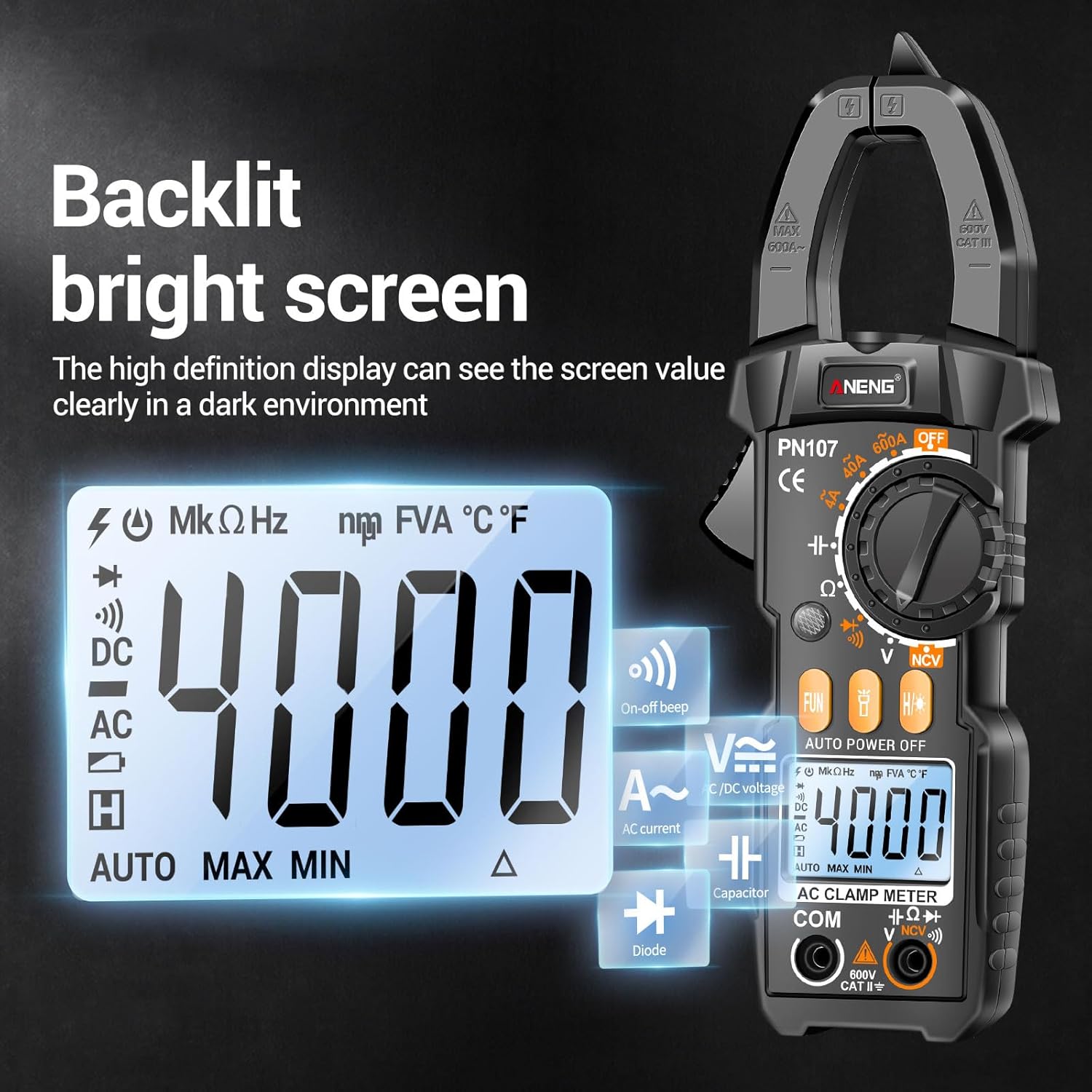
Figure 6: Backlit Bright Screen
This image highlights the clear, backlit display of the PN107 clamp meter, showing a reading of 4000 counts, which is easily visible even in dim environments.
5.8 Flashlight
The integrated flashlight can be activated by a dedicated button (refer to Figure 2 for location). It helps illuminate dark work areas, making it easier to identify wires and components.

Figure 7: Flashlight and Automatic Shutdown
This image illustrates two key features: the built-in flashlight, useful for finding lines in dim environments, and the automatic shutdown function, which powers off the device after 15 minutes of inactivity to save battery.
6. Maintenance
6.1 Cleaning
Wipe the meter's case with a damp cloth and mild detergent. Do not use abrasives or solvents. Keep the input jacks free of dust and debris.
6.2 Battery Replacement
When the low battery indicator appears on the display, replace the batteries immediately to ensure accurate readings. Refer to Section 4.1 for battery installation instructions.
6.3 Storage
If the meter is not to be used for a long period, remove the batteries to prevent leakage and damage to the device. Store the meter in a cool, dry place, away from direct sunlight and extreme temperatures.
7. Troubleshooting
| Problem | Possible Cause | Solution |
|---|---|---|
| Meter does not power on. | Dead or incorrectly installed batteries. | Check battery polarity; replace batteries. |
| No reading or "OL" displayed. | Overload, incorrect range, or open circuit. | Select higher range, check circuit connection, ensure clamp jaw is fully closed for current measurement. |
| Inaccurate readings. | Low battery, external interference, or incorrect function selected. | Replace batteries, move away from strong electromagnetic fields, verify function selection. |
| NCV not working. | No AC voltage present, or sensor not close enough. | Ensure AC voltage is present; bring sensor closer to the source. |
8. Specifications
| Parameter | Value |
|---|---|
| Model | PN107 |
| Material | ABS |
| AC Current | 0~600A, ±(2.5%+8), 1A |
| DC Voltage | 0~600V, ±(0.5%+3), 1V |
| AC Voltage | 0~600V, ±(1.0%+3), 1V |
| Resistance | 0~40MΩ, ±(1.5%+3), 0.01MΩ |
| Capacitance | 0~4mF, ±(5.0%+5), 0.001mF |
| Diode Test | Yes |
| Automatic Shutdown | Yes (15 minutes) |
| ON-off Beep (Continuity) | Yes |
| Data Retention (Hold) | Yes |
| NCV Indication | Yes |
| Flashlight | Yes |
| Backlit Screen | Yes |
| Screen Display | LCD screen |
| Maximum Count | 4000 count |
| Jaw Opening Size | 25mm / 0.98in |
| Power Supply | 2 * AAA Batteries (Not included) |
| Item Size | 194 * 50 * 30mm / 7.63 * 1.96 * 1.18in |
| Item Weight | 110.3g / 3.89oz |
| Product Dimensions (Package) | 8.35 x 4.33 x 1.97 inches |
| Manufacturer | Irfora |
| Country of Origin | China |
9. Warranty and Support
Specific warranty information for the Irfora PN107 Digital Clamp Meter is not available in the provided product data. Please refer to the product packaging or contact the seller/manufacturer directly for warranty details and customer support.
For further assistance, you may visit the Irfora brand page on Amazon.
Ask a question about this manual
Ask about setup, troubleshooting, compatibility, parts, safety, or missing instructions. Manuals+ will review the question and use this page’s manual context to help answer it.