Introduction
This manual provides essential information for the proper setup, operation, and maintenance of the Senzooe GY-BNO055 9DOF 9-axis BNO055 Breakout Board Sensor Module. Please read these instructions carefully before using the module to ensure correct functionality and to prevent damage.
Safety Information
- Handle the sensor module with care to avoid electrostatic discharge (ESD) damage.
- Ensure correct power supply voltage (typically 3.3V or 5V, refer to specifications) and polarity before connecting. Incorrect voltage can permanently damage the module.
- Avoid exposing the module to extreme temperatures, humidity, or corrosive environments.
- Do not apply excessive force when connecting or disconnecting wires.
Product Overview
The GY-BNO055 is a 9-axis sensor module integrating an accelerometer, gyroscope, and magnetometer, along with an ARM Cortex-M0 based processor for sensor fusion. It provides absolute orientation data in various modes, making it suitable for robotics, drones, and navigation applications.
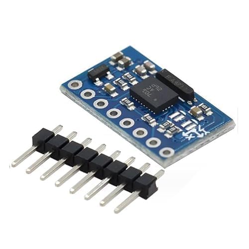
Figure 1: Senzooe GY-BNO055 9DOF 9-axis Sensor Module with included header pins.
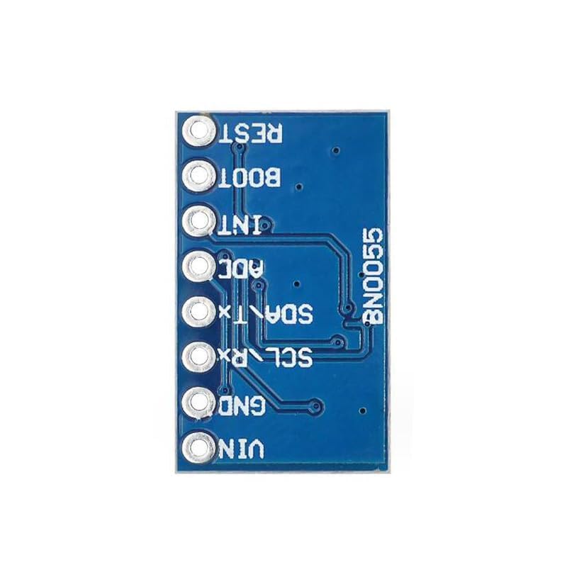
Figure 2: Bottom view of the GY-BNO055 module, illustrating the pinout for connections.
Specifications
| Feature | Description |
|---|---|
| Model Number | GY-BNO055 |
| Sensor Type | 9-axis (Accelerometer, Gyroscope, Magnetometer) |
| Interface | I2C (SDA, SCL), UART (TX, RX) |
| Number of Contacts | 20 (on breakout board) |
| Mounting Type | Plate mounting |
| Material | Plastic (for connector housing) |
| Dimensions | Approximately 20.5mm x 12.2mm (module board) |
| ASIN | B0D2J5PY29 |
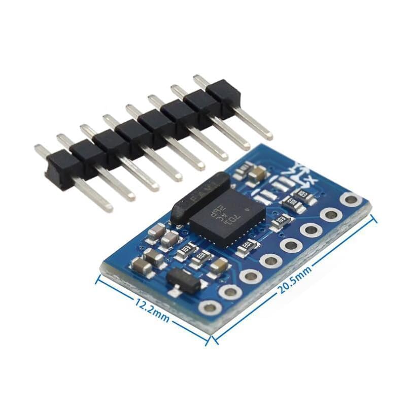
Figure 3: GY-BNO055 module dimensions for integration planning.
Setup
1. Pinout and Connections
The GY-BNO055 module features several pins for power, communication, and control. Refer to the pinout diagram (Figure 2) for identification.
- VIN: Power supply input (typically 3.3V to 5V, check BNO055 datasheet for exact range).
- GND: Ground connection.
- SCL/RX: I2C Clock Line / UART Receive.
- SDA/TX: I2C Data Line / UART Transmit.
- ADC: Analog-to-Digital Converter input (if available/used).
- INT: Interrupt output.
- BOOT: Boot mode selection pin.
- RST: Reset pin.
Connect the module to your microcontroller or development board according to the chosen communication protocol (I2C or UART). Ensure all connections are secure.
2. Software and Libraries
To interface with the BNO055, specific software libraries are typically required for your chosen programming environment (e.g., Arduino IDE, Python). Search for 'BNO055 library' relevant to your platform. These libraries handle the complex I2C/UART communication and sensor fusion algorithms, providing easily accessible orientation data.
Operating Instructions
1. Power On and Initialization
After connecting the module, apply power. The BNO055 will perform an internal self-test. Your software should then initialize the sensor, setting its operating mode (e.g., NDOF for 9-axis fusion, IMU for accelerometer/gyroscope only, COMPASS for magnetometer only). Refer to the BNO055 datasheet and your chosen library's documentation for specific mode configurations.
2. Calibration
For accurate readings, especially from the magnetometer, the BNO055 requires calibration. This typically involves moving the sensor through various orientations to map its magnetic environment. Most libraries provide functions to check calibration status and guide the user through the process. Ensure the sensor is calibrated in its final operating environment for best results.
3. Data Acquisition
Once initialized and calibrated, you can read various data types from the sensor, including:
- Euler Angles: Yaw, Pitch, Roll (orientation).
- Quaternions: More robust representation of orientation.
- Linear Acceleration: Acceleration without gravity.
- Gravity Vector: Direction of gravity.
- Angular Velocity: Rotational speed.
- Magnetic Field Strength: Raw magnetometer data.
Consult your library's examples for how to access these data points.
Maintenance
- Keep the module clean and free from dust and debris. Use a soft, dry brush or compressed air if necessary.
- Store the module in an anti-static bag when not in use, especially for extended periods.
- Avoid physical shock or vibration, which can affect sensor accuracy or cause damage.
- Periodically check connections for looseness or corrosion.
Troubleshooting
No Data or Incorrect Readings
- Check Connections: Verify all power, ground, and communication lines are correctly wired and secure.
- Power Supply: Ensure the module is receiving the correct voltage (e.g., 3.3V or 5V) and sufficient current.
- I2C/UART Address: Confirm the correct I2C address or UART baud rate is used in your software. The BNO055 typically has a default I2C address.
- Software Initialization: Ensure your code correctly initializes the BNO055 and sets the desired operating mode.
- Calibration: If orientation data is erratic, perform a full calibration of the sensor.
- Interference: Magnetic interference from motors, power lines, or other electronic components can affect magnetometer readings. Try to isolate the module from such sources.
Module Not Detected
- Wiring: Double-check all wiring, especially SDA/SCL or TX/RX lines.
- Power: Confirm the module is powered on.
- I2C Scanner: Use an I2C scanner sketch/program to detect if the module is present on the bus.
Warranty and Support
For warranty information or technical support, please refer to the retailer or manufacturer's official website where the product was purchased. Keep your proof of purchase for any warranty claims.