1. Introduction
This manual provides detailed instructions for the safe and effective operation of the Yuecoom DT266 Digital Clamp Meter. Please read this manual thoroughly before using the device to ensure proper function and to prevent potential hazards. Keep this manual for future reference.
1.1 Safety Information
- Always adhere to local and national safety codes.
- Do not use the meter if it appears damaged or if the test leads are damaged.
- Ensure the battery compartment is securely closed before operation.
- Avoid touching exposed wiring or terminals when power is applied.
- Do not attempt to measure voltages or currents exceeding the meter's specified maximum limits.
- Use caution when working with voltages above 30V AC RMS, 42V peak, or 60V DC, as these pose a shock hazard.
2. Product Features
The Yuecoom DT266 Digital Clamp Meter offers a range of functionalities for electrical testing:
- Smart NCV Testing: Non-Contact Voltage detection for identifying AC voltage presence without direct contact, enhancing safety.
- Wide Test Range: Capable of accurately measuring AC/DC voltage, AC current, resistance, and continuity.
- Good Clamp Design: Wide jaw allows for measuring large AC currents without interrupting circuits, suitable for mains cables and vehicle high current loads.
- Clear Digital Display: Ensures easy readability of measurements, improving accuracy and efficiency.
- Portable Design: Lightweight and compact for convenient outdoor use and on-the-go testing.
3. Package Contents
Upon opening the package, verify that all items listed below are present and undamaged:
- 1 x Yuecoom DT266 Digital Clamp Meter
- 2 x Test Probes (Red and Black)
- 1 x Storage Bag
- 1 x User Manual (This document)

Image 3.1: Contents of the Yuecoom DT266 Digital Clamp Meter package, including the meter, test probes, and a black storage bag.
4. Product Diagram and Components
Familiarize yourself with the different parts of your DT266 Digital Clamp Meter:

Image 4.1: A detailed diagram illustrating the key components of the DT266 Digital Clamp Meter, including the Current Measurement Jaw, Jaw Wrench, Functional Range Turntable, LCD Screen, Data Retention button, Red Probe Positive Test Socket, Black Lead Negative Test Socket, Insulation High Resistance EXT Test Socket, and Fail Resistant Lanyard.
- Current Measurement Jaw: Used for non-contact AC current measurement.
- Jaw Wrench: Activates the jaw opening mechanism.
- Functional Range Turntable: Selects the desired measurement function and range.
- LCD Screen: Displays measurement readings and indicators.
- Data Retention (HOLD) Button: Freezes the current reading on the display.
- Red Probe Positive Test Socket: Connection point for the red test lead.
- Black Lead Negative Test Socket (COM): Common connection point for the black test lead.
- Insulation High Resistance EXT Test Socket: Used for specific insulation resistance measurements (if applicable with optional accessories).
- Fail Resistant Lanyard: For securing the meter during use.
5. Setup
5.1 Battery Installation
- Ensure the meter is turned OFF.
- Locate the battery compartment cover on the back of the meter.
- Use a screwdriver to open the battery compartment.
- Insert one 9V (6F22) battery, observing the correct polarity (+/-).
- Replace the battery compartment cover and secure it with the screw.
5.2 Connecting Test Probes
For voltage, resistance, and continuity measurements, connect the test probes:
- Insert the black test lead into the 'COM' (Common) jack.
- Insert the red test lead into the 'VΩmA' jack (or the appropriate jack for the desired measurement).
6. Operating Instructions
Always select the appropriate function and range before making any measurement. If the measurement value is unknown, start with the highest range and work downwards.
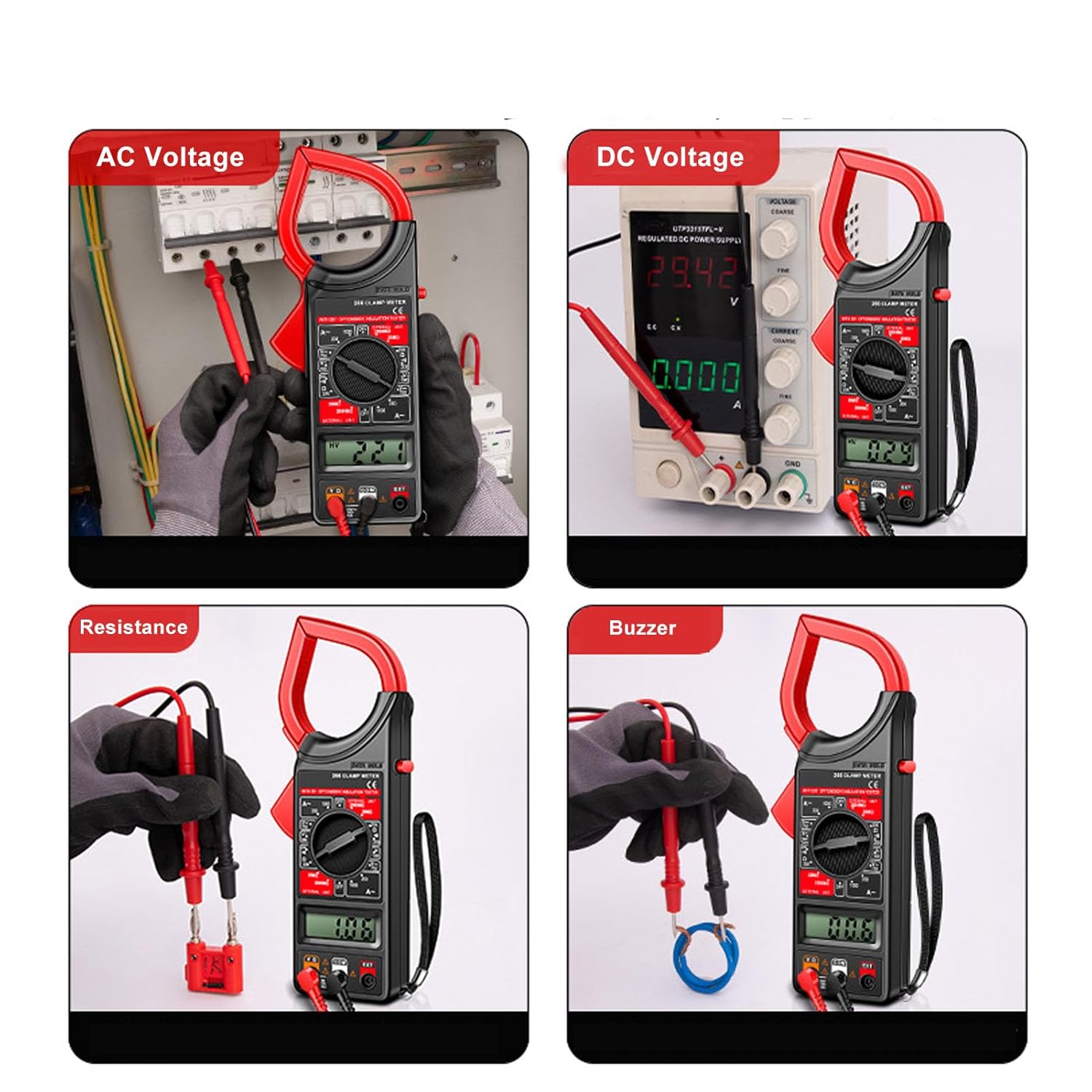
Image 6.1: Visual examples of the DT266 Digital Clamp Meter performing various measurements: AC Voltage, DC Voltage, Resistance, and Continuity (Buzzer) tests.
6.1 AC Current Measurement (Clamp Function)
- Turn the functional range turntable to the desired 'ACA' (AC Current) range (e.g., 200A or 1000A).
- Press the jaw wrench to open the clamp jaw.
- Enclose only one conductor of the circuit within the clamp jaw. Ensure the jaw is fully closed.
- Read the AC current value on the LCD screen.
6.2 AC/DC Voltage Measurement
- Connect the test probes as described in Section 5.2.
- Turn the functional range turntable to the desired 'ACV' (AC Voltage) or 'DCV' (DC Voltage) range.
- Touch the red probe to the positive side of the circuit and the black probe to the negative side (or neutral/ground for AC).
- Read the voltage value on the LCD screen.
6.3 Resistance Measurement
- Ensure the circuit or component to be measured is de-energized.
- Connect the test probes as described in Section 5.2.
- Turn the functional range turntable to the 'Ω' (Ohms) range.
- Touch the test probes across the component or circuit where resistance is to be measured.
- Read the resistance value on the LCD screen.
6.4 NCV (Non-Contact Voltage) Testing
The DT266 features NCV testing for detecting AC voltage without direct contact.
- Turn the functional range turntable to the NCV function (if available as a dedicated setting, otherwise the meter may automatically detect).
- Bring the top part of the clamp meter (near the jaw) close to the conductor or cable.
- The meter will indicate the presence of AC voltage, typically through an audible beep and/or visual indicator on the display.
6.5 Continuity Test (Buzzer)
- Ensure the circuit or component is de-energized.
- Connect the test probes as described in Section 5.2.
- Turn the functional range turntable to the continuity (buzzer) function, often indicated by a speaker icon.
- Touch the test probes across the circuit or component.
- If the resistance is below a certain threshold (typically 50Ω), the meter will emit an audible beep, indicating continuity.
7. Maintenance
7.1 Cleaning
- Wipe the meter with a dry, clean cloth. Do not use abrasives or solvents.
- Keep the test leads clean and free of debris.
7.2 Battery Replacement
When the battery low indicator appears on the display, replace the 9V battery as described in Section 5.1.
7.3 Storage
If the meter is not used for an extended period, remove the battery to prevent leakage and store the meter in its storage bag in a cool, dry place.
8. Troubleshooting
| Problem | Possible Cause | Solution |
|---|---|---|
| Meter does not turn on | Dead or incorrectly installed battery | Replace battery, check polarity |
| No reading or 'OL' displayed | Incorrect range selected; Open circuit; Measurement exceeds range | Select higher range; Check circuit continuity; Ensure proper connection |
| Inaccurate readings | Low battery; Dirty test leads; External interference | Replace battery; Clean leads; Move away from strong electromagnetic fields |
| Clamp jaw not closing properly | Obstruction in jaw mechanism | Inspect and clear any obstructions |
9. Specifications
- Model: DT266
- Material: ABS
- Power Supply: 1 x 6F22 9V Battery (not included)
- Item Weight: Approximately 0.35 Kilograms
- Date First Available: April 22, 2024
- Manufacturer: Yuecoom
For detailed measurement ranges and accuracy specifications, please refer to the markings on the device itself or contact customer support.
10. Warranty and Support
Yuecoom products are designed for reliability and performance. For warranty information, technical support, or service inquiries, please refer to the contact information provided with your purchase or visit the official Yuecoom store.
