1. Introduction
This manual provides instructions for the MokerLink 5 Port 2.5Gigabit Ethernet Switch with 2x10G SFP Slot. This unmanaged network switch is designed to expand your network capacity with high-speed 2.5G Ethernet and 10G SFP+ connectivity. It features a fanless metal design for quiet and stable operation, and supports VLAN isolation for improved network security and performance.

Image: Overview of the MokerLink 5 Port 2.5G Ethernet Switch, highlighting its 2.5Gbps ports, 10G SFP+ ports, plug-and-play functionality, port-based VLAN, and fanless design.
2. Product Overview
The MokerLink 5 Port 2.5Gigabit Ethernet Switch is equipped with 5x 2.5G Base-T Ethernet ports and 2x 10G SFP+ ports. The 2.5G ports are compliant with IEEE802.3bz and support adaptive speeds of 10/100/1000M/2.5G. The 10G SFP+ ports are compatible with 1G/2.5G/10G SFP modules (not included). The switch offers a 65Gbps backplane bandwidth for efficient data forwarding.

Image: Detailed view of the switch's front panel, showing 5x 2.5G RJ45 ports, 2x 10G SFP+ uplink ports, PWR indicator, LED indicators for port speed, and a DIP switch for VLAN mode.
2.1 Port Configuration and Indicators
- 5 x 2.5G Base-T Ports: RJ45 ports supporting 10/100/1000Mbps and 2.5Gbps.
- 2 x 10G SFP+ Ports: For fiber optic connections, compatible with 1G/2.5G/10G SFP modules.
- PWR Indicator: Illuminates when the device is powered on.
- Left LED (2.5G): Orange indicates 2.5Gbps connection.
- Right LED (10/100/1000M): Green indicates 10/100/1000Mbps connection.
- DIP Switch: Used to toggle between Default (Normal) Mode and VLAN Isolation Mode.
3. Specifications
| Brand | MokerLink |
| Model Number | 5x2.5G + 2x10G SFP |
| Number of Ports | 7 (5x 2.5G RJ45, 2x 10G SFP+) |
| Data Transfer Rate | 65 Gigabits Per Second (Backplane Bandwidth) |
| Switch Type | Unmanaged |
| Interface | RJ45, SFP |
| Compatible Devices | Desktop, Gaming Console, Server, NAS, WiFi 6 AP |
| Color | Black |
| Design | Metal, Fanless |
| Operating Temperature | -10°C to +55°C |
| Features | VLAN Isolation, Plug and Play, Auto MDI/MDIX, Auto-negotiation, 4KV Lighting Protection |
4. Package Contents
Verify that your package contains the following items:
- 1 x MokerLink 5 Port 2.5G Ethernet Switch
- 1 x Power Adapter (DC 12V/1A)
5. Setup Instructions
The MokerLink switch is designed for plug-and-play operation, requiring no complex configuration.
5.1 Physical Installation
- Placement: Place the switch on a stable, flat surface or mount it to a wall using the integrated mounting holes. Ensure adequate ventilation around the device.
- Power Connection: Connect the provided power adapter to the DC input port on the switch and then plug the adapter into a power outlet. The PWR LED will illuminate.

Image: The MokerLink switch mounted vertically on a wall next to a computer monitor, demonstrating its compact size and wall-mounting capability.
5.2 Network Connection
- Connect Devices: Use standard Ethernet cables (CAT5e, CAT6, or CAT6a recommended for 2.5G speeds) to connect your network devices (e.g., computers, NAS, WiFi 6 APs, gaming consoles) to any of the 5x 2.5G RJ45 ports.
- SFP+ Uplink (Optional): For 10G fiber optic connections, insert compatible SFP+ modules into the 2x 10G SFP+ slots and connect fiber optic cables to your server or core switch.
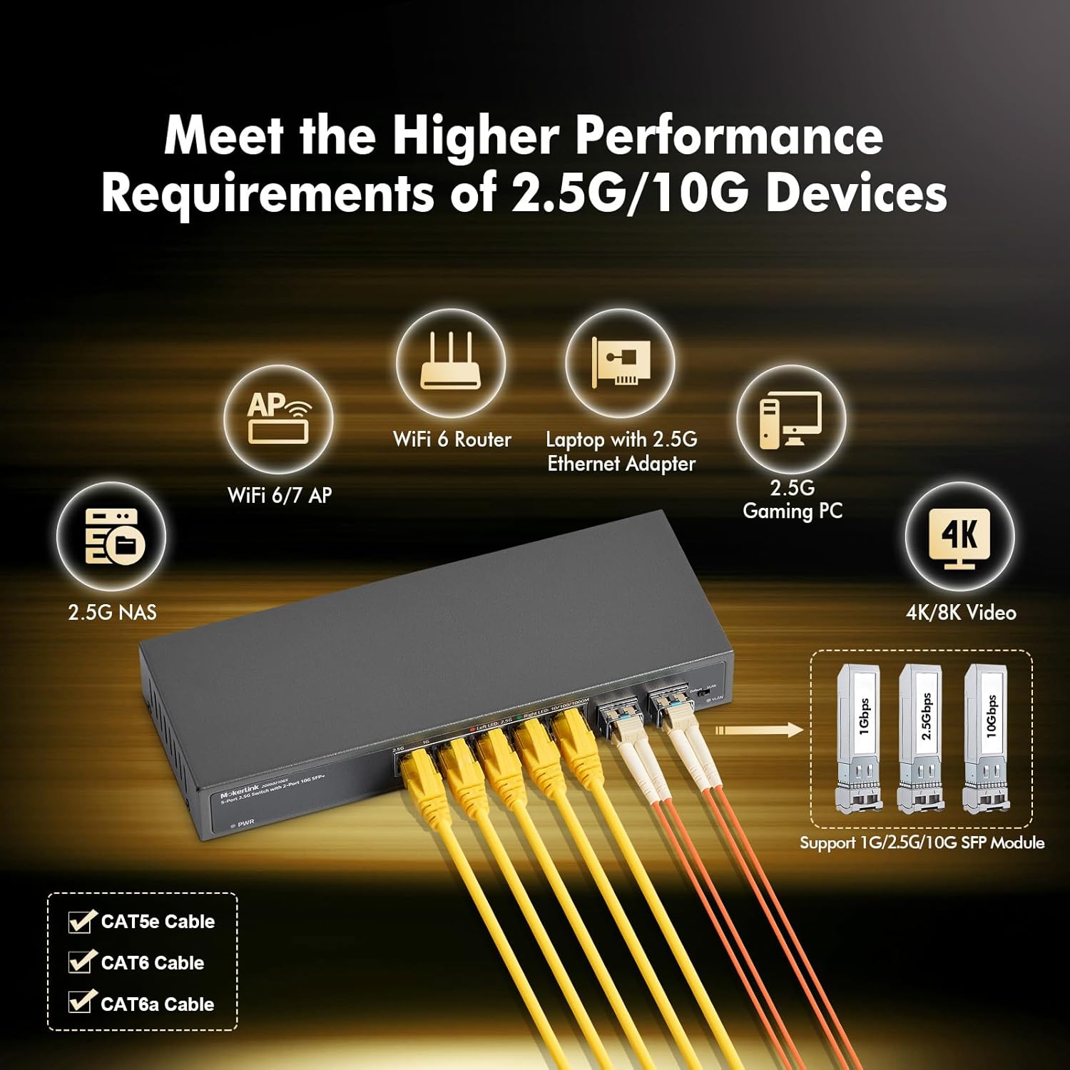
Image: The MokerLink switch connected via RJ45 cables to a WiFi 6 router, laptop, gaming PC, and NAS, and via SFP+ modules to other network infrastructure, illustrating its versatility.
The switch supports auto MDI/MDIX, so you do not need to worry about cable types (straight-through or crossover). It also features auto-negotiation, automatically detecting the link speed of connected devices.
6. Operating Instructions
6.1 LED Indicators
Monitor the status of your network connections using the LED indicators:
- PWR LED: Solid green indicates the switch is powered on.
- Left LED (2.5G) per port: Solid orange indicates a 2.5Gbps link. Blinking orange indicates data activity.
- Right LED (10/100/1000M) per port: Solid green indicates a 10/100/1000Mbps link. Blinking green indicates data activity.
6.2 VLAN Isolation Mode
The switch supports port-based VLAN isolation, which can reduce network storms and improve security by isolating traffic between specific ports. This is controlled by a DIP switch on the device.
- Default Mode (DIP switch in 'Default' position): All ports can communicate with each other.
- VLAN Mode (DIP switch in 'VLAN' position): Ports 1-5 are isolated from each other. Each of these ports can only communicate with the uplink ports (ports 6-7). This is useful for scenarios where you want to prevent direct communication between connected devices on ports 1-5, while still allowing them access to the wider network via the uplink ports.

Image: Diagram illustrating port-based VLAN isolation. In VLAN mode, devices connected to ports 1-5 are isolated from each other but can communicate with devices connected to uplink ports 6-7.
To change the VLAN mode, ensure the switch is powered off, adjust the DIP switch, and then power on the switch. Do not change the DIP switch position while the device is operating.
7. Maintenance
The MokerLink switch is designed for low maintenance due to its fanless and unmanaged nature.
- Cleaning: Keep the device clean and free from dust. Use a soft, dry cloth for cleaning. Do not use liquid or aerosol cleaners.
- Ventilation: Ensure that the ventilation holes are not blocked to prevent overheating, even though it is a fanless design.
- Power Cycle: If you experience network issues, a simple power cycle (unplugging and re-plugging the power adapter) can often resolve minor problems.
- Cable Management: Ensure all Ethernet and fiber optic cables are securely connected and not excessively bent or strained.
8. Troubleshooting
If you encounter issues with your MokerLink switch, refer to the following common troubleshooting steps:
- No Power: If the PWR LED is off, ensure the power adapter is securely connected to both the switch and a working power outlet. Try a different outlet if necessary.
- No Link Light: If a port's LED is off, check the Ethernet cable connection at both ends. Try a different cable or port. Ensure the connected device is powered on and functioning correctly.
- Slow Speed: If you are not achieving expected speeds (e.g., 2.5G), verify that both the connected device and the Ethernet cable (CAT5e, CAT6, or CAT6a) support the desired speed. Check the port's LED indicator to confirm the link speed.
- Network Connectivity Issues: If devices cannot communicate, check the DIP switch position. If VLAN mode is enabled, devices on ports 1-5 cannot communicate directly with each other. Switch to Default mode if direct communication is required.
- Intermittent Connection: Check for loose cable connections. Ensure the switch is placed in an environment within its specified operating temperature range (-10°C to +55°C).
9. Warranty Information
The MokerLink 5 Port 2.5Gigabit Ethernet Switch comes with a 1-Year Warranty from the date of purchase. This warranty covers defects in materials and workmanship under normal use. It does not cover damage caused by misuse, accidents, unauthorized modifications, or external factors such as power surges.
Please retain your proof of purchase for warranty claims.
10. Support
For further assistance or technical support, please refer to the official MokerLink website or contact their customer service department. Contact information can typically be found on the product packaging or the manufacturer's official website.
When contacting support, please have your product model number (5x2.5G + 2x10G SFP) and a detailed description of your issue ready.