1. Introduction
This manual provides detailed instructions for the installation, operation, and maintenance of the Aoleaby JK Smart BMS B1A8S20P. This Battery Management System is designed to protect and optimize the performance of various lithium battery types, including Li-ion, LiFePO4, and LTO, supporting configurations from 4S to 8S. It features active balancing, Bluetooth (BT) and RS485 communication, and comprehensive protection functions.
2. Key Features
- JK Own Development APP: Utilize the dedicated mobile application for detailed BMS settings and real-time battery status monitoring via Bluetooth communication.
- JK Active Balance: The smart active balancing feature equalizes voltage differences between battery cells, enhancing battery usage efficiency up to 99% and extending battery lifespan.
- Full Functionality Protection: Provides robust protection against over-charge, over-discharge, over-current, short circuit, and includes a low-temperature charging cutoff.
- Wide Compatibility: Supports 4S to 8S battery string configurations for Li-ion, LiFePO4, and LTO battery systems.
- High Current Capacity: Offers a continuous output current of up to 200A and a peak current of 350A, with an active balance current of 1A.
- Communication Interfaces: Equipped with Bluetooth (BT) and RS485 for versatile connectivity and data exchange.
3. Package Contents
Verify that all items listed below are present and in good condition upon opening the package.
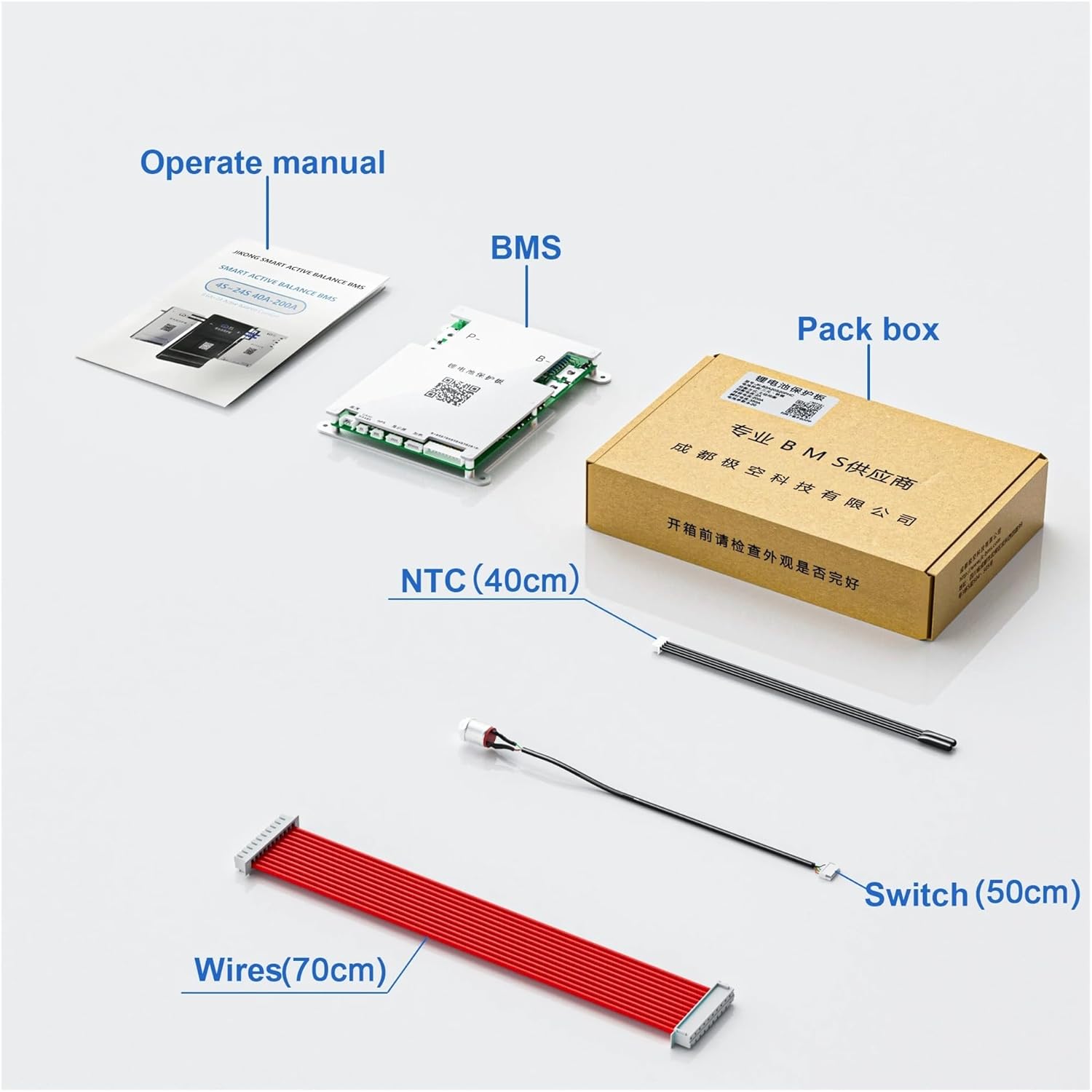
Image Description: This image displays the typical package contents: the BMS unit, an operation manual, an NTC temperature sensor (40cm), a switch (50cm), and a set of wiring harnesses (70cm). The packaging box is also visible.
- JK Smart BMS B1A8S20P Module
- Operation Manual
- NTC Temperature Sensor (40cm)
- Control Switch (50cm)
- Wiring Harnesses (70cm)
4. Installation and Wiring
Proper installation is crucial for the safe and effective operation of the BMS. Follow these steps carefully.

Image Description: This image displays the Aoleaby JK Smart BMS B1A8S20P module, showing its metallic casing and circuit board. Key terminals 'P-' and 'B-' are visible, along with a QR code for app download and instructions. The module also features labels for CAN/RS485, GPS, Display, and Heating functions. For app download, scan the QR code or visit http://qr17.cn/BApbC0.

Image Description: This image highlights the key features of the B1A8S20P BMS, including BT/RS485 communication, 1A balance current, support for 4S-8S battery strings, 200A charge/discharge current, dimensions (153*186*18mm), and compatibility with Li-ion/LiFePO4/LTO battery types. The product module is shown on the right. For more information, scan the QR code or visit http://qr17.cn/BApbC0.

Image Description: A side view of the Smart Active Balance BMS, showing the product label with details such as Type: JK-B1A8S20P, Battery Type: Li-ion/LiFePO4/LTO, Balance Method: Active Balance, Balance Current: 1A, Continuous Current: 200A, Peak Current: 350A, and Battery Strings: 4S-8S. A QR code is also present on the label.
4.1 Wiring Diagram
Refer to the following diagram for correct connection of the BMS to your battery pack and load/charger.

Image Description: A detailed wiring diagram illustrating how to connect the JK Smart BMS to a battery pack. It shows connections for the total positive pole (B+), total negative electrode, individual battery strings (1st, 2nd, 3rd, last string), and outputs for motor/load and charger. The BMS module is depicted in the center of the diagram. For detailed instructions, scan the QR code or visit http://qr17.cn/BApbC0.
- Connect the B- terminal of the BMS to the total negative pole of the battery pack.
- Connect the P- terminal of the BMS to the negative terminal of your load (motor, inverter, etc.) and charger.
- Connect the individual cell balance wires from the battery pack to the corresponding ports on the BMS. Ensure correct order from the lowest cell voltage to the highest.
- Connect the NTC temperature sensor to the designated port on the BMS and place the sensor on a battery cell for accurate temperature monitoring.
- Connect the control switch to its designated port. This switch can be used to activate/deactivate the BMS.
Important: Always connect the balance wires before connecting the main power cables (B- and P-). Disconnect in reverse order.
5. Operating Instructions
5.1 Mobile Application (APP) Usage
The JK Smart BMS features a dedicated mobile application for comprehensive monitoring and control. To download the app, scan the QR code on the BMS module or refer to the provided link in the image descriptions.

Image Description: A mobile phone screen displays the JK Smart BMS application interface. The app shows real-time battery data including charge/discharge status, voltage, current, capacity, cycle count, cell voltages, temperature, and balance status. This demonstrates the app's monitoring capabilities.
- Download and Install: Download the JK BMS app from your device's app store or by scanning the QR code.
- Connect via Bluetooth: Enable Bluetooth on your smartphone and open the JK BMS app. The app will search for nearby BMS devices. Select your BMS from the list to connect.
- Monitor Data: Once connected, the app displays real-time battery data, including total voltage, individual cell voltages, charge/discharge current, temperature, state of charge (SOC), and cycle count.
- Adjust Parameters: The app allows you to modify various BMS parameters such as over-voltage protection, under-voltage protection, over-current limits, and temperature thresholds. Exercise caution when adjusting these settings.
- Control Balance Switch: You can enable or disable the active balance function directly from the app.
5.2 Active Balance Function
The active balance feature works continuously to equalize the voltage across all battery cells. This process helps prevent cell degradation due to imbalance and maximizes the overall capacity and lifespan of the battery pack. The 1A balance current ensures efficient balancing for various battery sizes.
6. Specifications
| Feature | Specification |
|---|---|
| Model | B1A8S20P |
| Supported Battery Types | Li-ion, LiFePO4, LTO |
| Battery String Configuration | 4S - 8S |
| Continuous Output Current | Up to 200A |
| Peak Current | 350A |
| Active Balance Current | 1A |
| Communication | Bluetooth (BT), RS485 |
| Protection Functions | Over-charge, Over-discharge, Over-current, Short Circuit, Low Temperature Charging Cutoff |
| Dimensions (L x W x H) | 153 x 186 x 18 mm (approximate) |
| Item Weight | 2.2 pounds (1000 grams) |
7. Troubleshooting
This section addresses common issues you might encounter with your JK Smart BMS.
- BMS Not Powering On:
- Check all wiring connections, especially B- and P-, for secure contact.
- Ensure the battery pack voltage is within the operational range for the BMS.
- Verify the control switch is in the 'ON' position.
- App Not Connecting via Bluetooth:
- Ensure Bluetooth is enabled on your smartphone.
- Make sure the BMS is powered on.
- Try restarting the app and rescanning for devices.
- Ensure no other device is currently connected to the BMS via Bluetooth.
- Battery Cells Imbalanced:
- Confirm that all balance wires are correctly connected to the BMS and individual cells.
- Check the app to ensure the active balance function is enabled.
- Allow sufficient time for the active balance to work, especially if the imbalance is significant.
- Over-current/Short Circuit Protection Triggered:
- Identify and remove the source of the over-current or short circuit.
- The BMS will typically reset automatically once the fault is cleared. If not, cycle the power to the BMS.
8. Maintenance
Regular maintenance helps ensure the longevity and optimal performance of your BMS.
- Regular Inspection: Periodically inspect all wiring connections for tightness and signs of corrosion or damage.
- Cleanliness: Keep the BMS module clean and free from dust and debris. Use a dry, soft cloth for cleaning.
- Temperature Monitoring: Ensure the BMS operates within its specified temperature range. Avoid extreme heat or cold.
- Firmware Updates: Check the manufacturer's website or app for any available firmware updates for improved performance or new features.
9. Warranty and Support
For warranty information and technical support, please refer to the documentation provided with your purchase or contact Aoleaby customer service directly. Keep your purchase receipt as proof of purchase for warranty claims.


