1. Introduction
This manual provides essential instructions for the safe and efficient use of your Aoleaby JK Smart BMS (Battery Management System) models BD6A20S15P and BD6A24S15P. The JK Smart BMS is designed to manage and protect various battery chemistries, including LiFePO4, Li-Ion, and LTO, ensuring optimal performance and longevity. Please read this manual thoroughly before installation and operation.
2. Product Overview
The JK Smart BMS is an advanced battery management system featuring active balancing capabilities. It monitors and controls individual battery cells to maintain voltage consistency, thereby extending battery life and improving overall system efficiency. This BMS offers comprehensive protection against common battery issues.

Image 1: Front view of the JK Smart BMS BD6A20S15P, highlighting BT/RS485 function, 0.6A balance current, 8S-20S battery strings support, 150A charge/discharge current, dimensions (162*102*20mm), and compatibility with Li-ion/LiFePO4/LTO battery types.
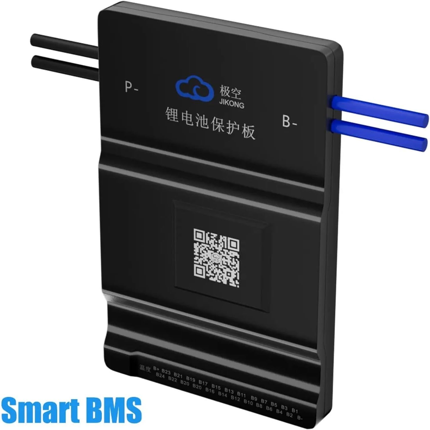
Image 2: Rear view of the JK Smart BMS BD6A24S15P, showing model type, battery type compatibility, active balance method, 0.6A balance current, 150A continuous current, 300A peak current, and 8S-24S battery string support.
3. Key Features
- Bluetooth (BT) Communication: Connects to a dedicated mobile application for real-time battery status monitoring and BMS settings adjustment.
- Active Balance Function: Actively balances voltage differences between battery cells, improving battery usage efficiency up to 99% and extending battery lifespan.
- Comprehensive Protection: Provides protection against over-charge, over-discharge, over-current, short circuit, and low-temperature charging cutoff.
- Wide Compatibility: Supports various battery configurations including 8S, 12S, 14S, 16S, 17S, 20S, and 24S for LiFePO4, Li-Ion, and LTO battery systems.
- High Current Support: Capable of handling continuous currents from 40A to 200A, with peak currents up to 350A depending on the model.
4. Package Contents
Verify that all items are present and undamaged upon opening the package:

Image 3: Contents of the JK Smart BMS package, including the BMS unit, an operating manual, a package box, NTC temperature sensor (40cm), a switch (50cm), and balance wires (70cm).
- JK Smart BMS Unit
- Operating Manual
- NTC Temperature Sensor (40cm)
- Switch (50cm)
- Balance Wires (70cm)
5. Setup and Installation
Important: Installation should only be performed by individuals with appropriate electrical knowledge. Incorrect wiring can cause damage to the BMS, battery, or connected equipment, and poses a safety risk.
5.1 Safety Precautions
- Always disconnect the battery pack from any loads or chargers before installing the BMS.
- Wear appropriate personal protective equipment (PPE), including insulated gloves and eye protection.
- Ensure all connections are secure and properly insulated to prevent short circuits.
- Verify battery cell polarity before connecting balance wires.
5.2 Wiring Diagram
Follow the wiring diagram carefully for correct installation. The diagram illustrates the connection points for the battery pack, balance wires, main positive (B+), main negative (B-), charge (P-), and load (P-).

Image 4: Detailed wiring diagram showing connections for the battery pack (1st string, second string, third string, last string), total positive pole (B+), total negative electrode, sampling cable, and output terminals for motor/load and charger (P- and B-).
- Connect the main negative (B-) terminal of the BMS to the total negative electrode of the battery pack.
- Connect the balance wires (sampling cable) from the BMS to each individual cell or cell group, starting from the first string (B1) up to the last string (B+). Ensure correct polarity for each connection.
- Connect the main positive (B+) terminal of the battery pack to the designated B+ input on the BMS (if applicable, or directly to the system).
- Connect the load (motor, inverter, etc.) and charger to the P- terminal of the BMS and the main positive (B+) of the battery pack.
- Connect the NTC temperature sensor to the BMS and place the sensor on a battery cell to monitor temperature.
- Connect the switch to the designated port on the BMS. This switch can be used to enable/disable the BMS or certain functions.
6. Operating Instructions
6.1 Initial Power-Up
After completing all wiring, carefully double-check all connections. Power on the BMS using the connected switch (if provided) or by connecting the battery pack. The BMS should initialize, and you may observe indicator lights.
6.2 Using the Smart BT APP
The JK Smart BMS features Bluetooth connectivity, allowing you to monitor and configure the system via a dedicated mobile application. The app is compatible with both Android and iOS devices.

Image 5: Screenshot of the Smart BT APP interface, demonstrating real-time monitoring of battery data, support for modifying related parameters, control of the BMS balance switch, and compatibility with Android and iOS systems. The app displays individual cell voltages, charge/discharge status, capacity, cycle count, and temperature.
- Download the APP: Scan the QR code on the BMS unit or in the manual, or search for "JK BMS" in your device's app store. A direct link is available here: http://qr17.cn/BApbC0
- Connect via Bluetooth: Enable Bluetooth on your mobile device. Open the JK BMS app and search for available BMS devices. Select your BMS to connect.
- Monitor Data: The app will display real-time battery data, including total voltage, individual cell voltages, charge/discharge current, temperature, state of charge (SOC), and cycle count.
- Adjust Parameters: Access the settings menu within the app to modify various BMS parameters such as over-voltage protection, under-voltage protection, over-current limits, and balancing thresholds. Exercise caution when changing settings.
- Control Balance Switch: The app allows you to control the active balance function, enabling or disabling it as needed.
7. Maintenance
Proper maintenance ensures the longevity and reliability of your BMS and battery system.
- Regular Inspection: Periodically inspect all wiring connections for looseness, corrosion, or damage.
- Cleanliness: Keep the BMS unit clean and free from dust and moisture. Do not use harsh chemicals for cleaning.
- Temperature Monitoring: Regularly check battery and BMS temperatures, especially during charging and discharging, to ensure they remain within safe operating limits.
- Firmware Updates: Check the manufacturer's website or app for any available firmware updates for the BMS.
8. Troubleshooting
This section addresses common issues you might encounter with your JK Smart BMS.
8.1 Common Issues and Solutions
- BMS Not Powering On:
- Check main battery connections (B- and B+).
- Verify the switch connection and its state.
- Ensure the battery pack voltage is within the BMS's operating range.
- APP Not Connecting to BMS:
- Ensure Bluetooth is enabled on your phone.
- Make sure the BMS is powered on and within Bluetooth range.
- Restart the app and try reconnecting.
- Check if the BMS is already connected to another device.
- Cell Voltage Imbalance:
- Confirm all balance wires are correctly connected and secure.
- Check the active balance function status in the APP.
- Allow sufficient time for the active balancing to work, especially with large imbalances.
- Over-Current/Short Circuit Protection Triggered:
- Identify and remove the source of the over-current or short circuit.
- The BMS will typically reset automatically once the fault is cleared. If not, cycle the power.
- Ensure your load current does not exceed the BMS's continuous current rating.
9. Specifications
| Feature | Specification |
|---|---|
| Model Numbers | BD6A20S15P / BD6A24S15P |
| Supported Battery Types | LiFePO4, Li-Ion, LTO |
| Cell Configuration | 8S - 24S (varies by model, e.g., 8S-20S for BD6A20S15P, 8S-24S for BD6A24S15P) |
| Continuous Current | 150A (up to 200A for some variants) |
| Peak Current | 300A (up to 350A for some variants) |
| Active Balance Current | 0.6A - 2A |
| Communication Interface | Bluetooth (BT), RS485 |
| Dimensions (approx.) | 162 x 102 x 20 mm (for BD6A20S15P) |
| Weight (approx.) | 2.2 pounds (1000 grams) |
10. Warranty and Support
Specific warranty details are typically provided with your purchase documentation or on the manufacturer's official website. For technical support, troubleshooting assistance, or warranty claims, please contact your retailer or the manufacturer directly. Ensure you have your product model number and purchase date available when seeking support.


