1. Introduction
This manual provides essential information for the safe and efficient installation, operation, and maintenance of your ACLDOYYV 3 Inch Motorized Three Way Ball Valve, model Q941/45F-16P. Please read this manual thoroughly before attempting any installation or operation to ensure proper function and to prevent damage or injury. Keep this manual for future reference.
2. Safety Information
WARNING: Failure to follow these safety instructions could result in serious injury, property damage, or death.
- Always disconnect power before performing any installation, maintenance, or troubleshooting.
- Installation and wiring should only be performed by qualified personnel in accordance with local electrical and plumbing codes.
- Ensure the valve's pressure rating is suitable for the application.
- Wear appropriate personal protective equipment (PPE) during installation and maintenance.
- Do not operate the valve beyond its specified voltage or temperature limits.
- Verify that the system is depressurized before working on the valve.
3. Product Overview
The ACLDOYYV Q941/45F-16P is a 3-inch motorized three-way ball valve constructed from stainless steel, designed for reliable flow control in various industrial and commercial applications. It features female threaded connections and is available with electric actuators for DC24V or AC220V power supplies. The valve supports both T-type and L-type flow configurations, allowing for diversion or mixing of media.
3.1 Key Features
- Material: High-quality Stainless Steel for corrosion resistance.
- Size: 3 Inch female threaded connections.
- Actuation: Electric motorized actuator for automated operation.
- Voltage Options: Compatible with DC24V or AC220V power supplies.
- Flow Type: Three-way design with T-type or L-type port configurations for versatile flow control.
3.2 Components
The valve consists of two main parts: the ball valve body and the electric actuator.
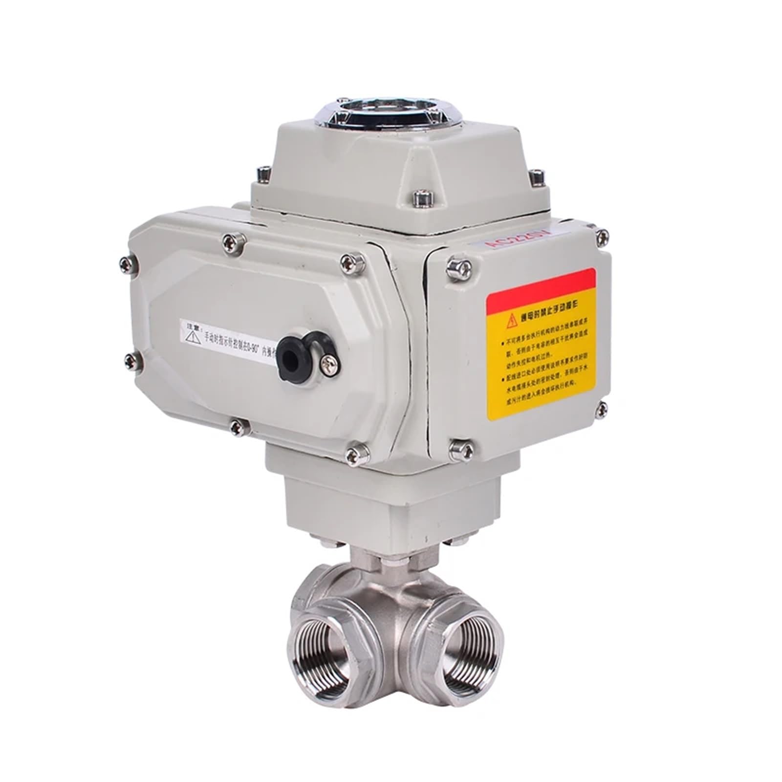
Figure 1: General view of the ACLDOYYV 3 Inch Motorized Three Way Ball Valve. This image shows the complete assembly, including the stainless steel valve body with female threaded ports and the grey electric actuator mounted on top.

Figure 2: Side view of the motorized ball valve. This perspective highlights the robust construction of both the valve body and the electric actuator, showing the connection points.

Figure 3: Detail of the electric actuator. This image shows the position indicator window, which displays the current open/closed status of the valve, and a label indicating 'AC220V' for the power supply type.

Figure 4: Close-up of the valve body's female threaded ports. This view clearly shows the internal threading for connection to pipes and the 'CF8M 1000WOG' marking, indicating material and pressure rating.
4. Specifications
| Parameter | Value |
|---|---|
| Model Number | Q941/45F-16P |
| Brand | ACLDOYYV |
| Valve Size | 3 Inch |
| Material | Stainless Steel |
| Valve Type | Three Way Ball Valve (T/L Type) |
| Connection Type | Female Thread |
| Actuator Type | Electric Motorized |
| Voltage Options | DC24V, AC220V |
| Item Weight | 1.76 ounces (Note: This weight appears to be for packaging or a small component. Actual product weight for a 3-inch stainless steel valve will be significantly higher.) |
| Package Dimensions | 1.18 x 0.79 x 0.39 inches (Note: These dimensions appear to be for packaging or a small component. Actual product dimensions for a 3-inch valve will be larger.) |
5. Setup and Installation
Proper installation is crucial for the valve's performance and longevity. Ensure all safety precautions are followed.
5.1 Pre-Installation Checks
- Inspect the valve for any shipping damage.
- Verify that the valve's specifications (size, material, pressure, voltage) match your system requirements.
- Ensure the pipeline is clean and free of debris that could damage the valve seats.
5.2 Mechanical Installation
- Install the valve in the correct flow direction as indicated by markings on the valve body (if present). For three-way valves, consider the desired flow path (T-type or L-type).
- Use appropriate thread sealant on the female threaded connections.
- Tighten connections securely, but do not overtighten, which can damage the threads or valve body.
- Support the valve and piping adequately to prevent stress on the connections.
- Ensure sufficient clearance around the actuator for maintenance and operation.
5.3 Electrical Wiring
CAUTION: Electrical wiring must be performed by a qualified electrician.
- Ensure the power supply matches the actuator's voltage (DC24V or AC220V).
- Refer to the wiring diagram provided on the actuator or within its terminal box cover.
- Connect the power supply wires to the designated terminals. Ensure proper grounding.
- Secure all wiring connections and ensure the terminal box cover is properly sealed to prevent moisture ingress.
- Test the electrical connections before applying full system pressure.
6. Operating Instructions
The motorized actuator allows for remote or automated control of the valve's position.
6.1 Basic Operation
- Apply power to the actuator according to the wiring diagram.
- The actuator will move the ball to the desired position (e.g., fully open, fully closed, or diverted).
- The position indicator on the actuator provides visual confirmation of the valve's current state.
6.2 T-Type vs. L-Type Flow
The three-way ball valve can be configured for T-type or L-type flow paths, depending on the internal ball design and actuator rotation.
- L-Type Flow: Allows flow from one inlet to either of two outlets, or blocks flow entirely. It can divert flow but cannot mix.
- T-Type Flow: Allows flow from one inlet to both outlets simultaneously, or from two inlets to one outlet (mixing), or from one inlet to another outlet (diversion).
Consult your system design and the specific valve's internal ball configuration to understand its flow capabilities.
7. Maintenance
Regular maintenance ensures optimal performance and extends the lifespan of your valve.
- Inspection: Periodically inspect the valve and actuator for signs of leakage, corrosion, or damage. Check electrical connections for tightness.
- Cleaning: Keep the exterior of the actuator clean and free of dust or debris. Do not use harsh chemicals that could damage the housing.
- Actuator Function: Cycle the valve periodically to ensure the actuator operates smoothly through its full range of motion.
- Seals: If leakage occurs from the valve body, it may indicate worn seals. Replacement should be performed by qualified personnel.
- Storage: If storing the valve for an extended period, ensure it is clean, dry, and protected from extreme temperatures and corrosive environments.
8. Troubleshooting
Before attempting any troubleshooting, ensure power is disconnected and the system is depressurized.
| Problem | Possible Cause | Solution |
|---|---|---|
| Valve does not move | No power to actuator Incorrect wiring Actuator motor failure | Check power supply and circuit breaker Verify wiring against diagram Contact technical support |
| Valve leaks from connections | Improperly tightened threads Damaged thread sealant | Retighten connections (ensure system is depressurized) Reapply thread sealant |
| Valve leaks from stem/body | Worn seals Valve body damage | Contact technical support for seal replacement or valve repair/replacement |
| Actuator makes noise but valve doesn't move | Obstruction in valve Gearbox issue in actuator | Depressurize and inspect valve for obstructions Contact technical support |
9. Warranty and Support
For warranty information or technical assistance, please contact your supplier or the manufacturer directly. Provide your product model number (Q941/45F-16P) and purchase details when seeking support.