1. Introduction
The AVIMYA ETC-974 is a versatile temperature controller designed for precise temperature management in various applications, including refrigeration, defrosting, and heating control. It features dual NTC sensors for accurate temperature measurement and a clear digital display for easy monitoring. This manual provides essential information for the safe and effective installation, operation, and maintenance of your ETC-974 temperature controller.

Figure 1: ETC-974 Temperature Controller in various applications.
Package Contents
- ETC-974 Temperature Controller Unit
- 2 NTC Sensors (2 meters each)
- User Manual

Figure 2: Package contents of the ETC-974.
2. Product Overview
The ETC-974 features a compact design for embedded installation, making it suitable for integration into various control panels. Its intuitive interface allows for easy temperature monitoring and function switching.
Key Features
- Dual NTC Sensor Input
- Temperature Control for Refrigeration, Defrosting, and Heating
- High Precision Inductor for stable performance
- Embedded Installation Design
- Upper and Lower Temperature Limit Settings
- High and Low Temperature Alarm Functions

Figure 3: ETC-974 key features.
Front Panel Description
The front panel of the ETC-974 includes a digital display and several control buttons:
- Digital Display: Shows current temperature and parameter values.
- Up Button (⇧): Used to increase values or navigate menus.
- Down Button (⇩): Used to decrease values or navigate menus.
- FNC (Function) Button: Used to switch between different operating functions (refrigeration, defrosting, etc.).
- SET Button: Used to enter parameter setting mode and confirm selections.
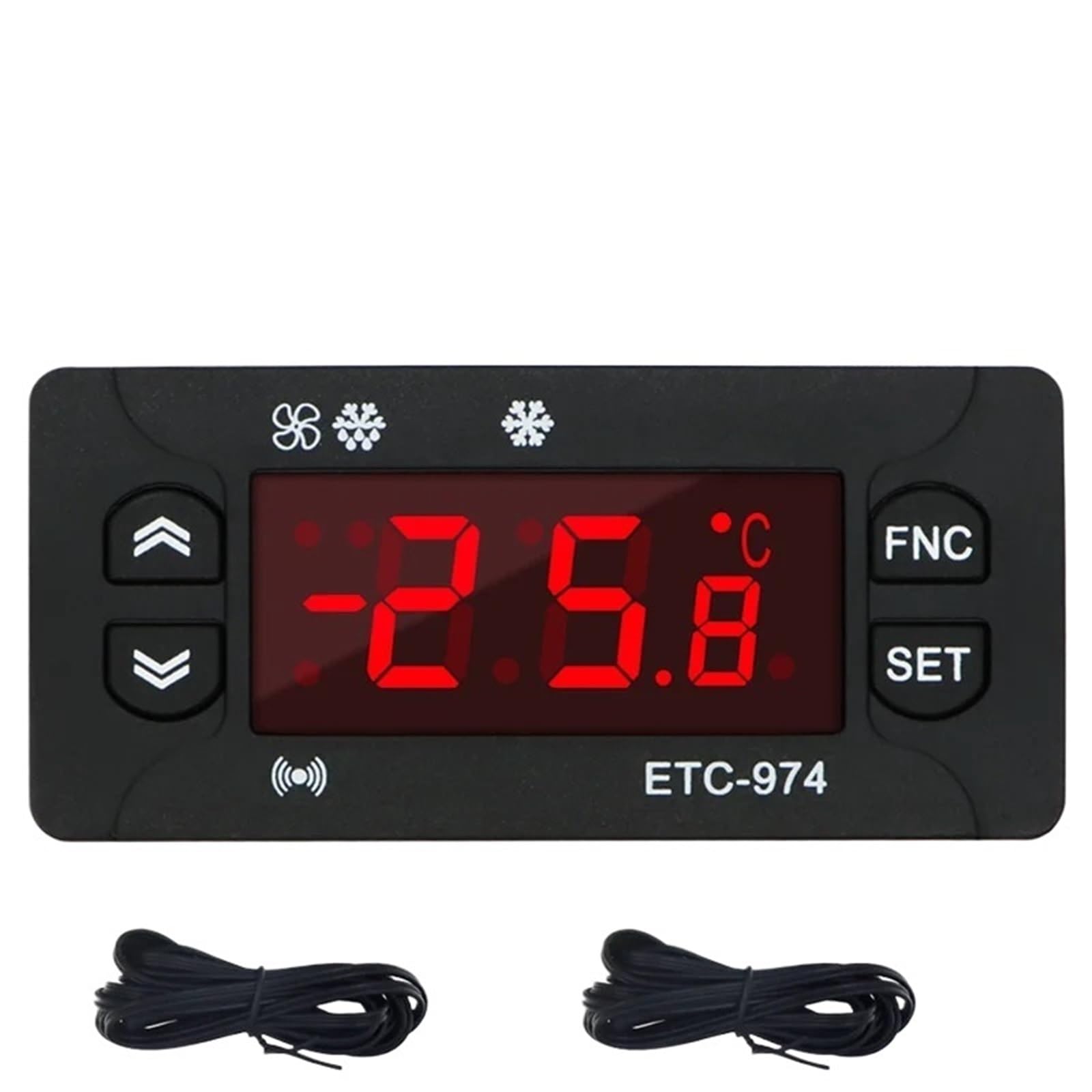
Figure 4: ETC-974 Front Panel and Controls.
3. Specifications
| Parameter | Value |
|---|---|
| Model | ETC-974 |
| Temperature Measure Range (NTC) | -50℃ to 110℃ (-58℉ to 230℉) |
| Display Resolution | 1℃ / 0.1℃ (switchable) |
| Accuracy (NTC) | ±0.5℃ (-30℃ to 50℃); ±1℃ (other ranges) |
| Probe Type | NTC (-50℃ to 120℃) |
| Power Supply | 230VAC ±10%; 50/60Hz |
| Rated Current of Relays (Refrigeration, Defrost, Fan) | 8A / 220VAC |
| Operating Temperature | -5℃ to 55℃ |
| Relative Humidity | 10% - 90% RH (non-condensing) |
| Storage Temperature | -30℃ to 85℃ |
| Input | 2 NTC Sensors |
| Sensor Length | 2M (including probe) |
| Product Dimensions (L*W*H) | 77mm * 34.5mm * 58mm (approx. 3.03 x 1.36 x 2.28 inches) |
| Mounting Size | 71mm * 29mm (approx. 2.80 x 1.14 inches) |
| Item Weight | 50 Grams (approx. 1.76 ounces) |
4. Installation
The ETC-974 is designed for embedded installation. Ensure the mounting hole dimensions are 71mm x 29mm. Before proceeding with installation, ensure the power supply is disconnected to prevent electrical shock.
Wiring Diagram
Carefully follow the wiring diagram below to connect the power supply, sensors, and controlled loads (refrigeration compressor, defrost heater, fan). Incorrect wiring can damage the unit or connected equipment.

Figure 5: ETC-974 Wiring Diagram.
- Power Supply: Connect 230VAC power to the designated terminals.
- NTC Sensors (Pb1, Pb2): Connect the two NTC sensors to their respective terminals. These sensors measure the temperature.
- Defrost Output: Connect the defrost heater to the defrost relay output.
- Compressor Output (Comp.): Connect the refrigeration compressor to the compressor relay output.
- Fan Output: Connect the fan to the fan relay output.
Warning: All wiring should be performed by a qualified electrician and in accordance with local electrical codes. Ensure proper grounding.
5. Operation
Basic Operation
- Power On: After correct installation and wiring, apply power to the unit. The display will show the current temperature.
- Start Temperature Control: Press and hold the SET key for a few seconds to initiate the temperature control process.
- Switch Functions: Press the FNC (Function) key to cycle through different operating modes, such as refrigeration, defrosting, and heating.
Setting Parameters
To adjust temperature setpoints, differential, alarm limits, and other operational parameters:
- Press and hold the SET key until the display shows the first parameter code.
- Use the Up (⇧) and Down (⇩) buttons to navigate through the parameter codes.
- Press the SET key to view the value of the selected parameter.
- Use the Up (⇧) and Down (⇩) buttons to modify the parameter value.
- Press the SET key again to confirm the new value and save it.
- To exit the parameter setting mode, press the FNC key or wait for a timeout.
Refer to the detailed parameter list in the included user manual for specific parameter codes and their functions.
6. Maintenance
Regular maintenance ensures the longevity and optimal performance of your ETC-974 Temperature Controller.
- Cleaning: Periodically wipe the front panel with a soft, dry cloth. Do not use abrasive cleaners or solvents.
- Sensor Inspection: Ensure the NTC sensors are clean and free from damage. Verify their placement for accurate temperature readings.
- Ventilation: Ensure adequate airflow around the controller if it is not fully enclosed, to prevent overheating.
- Power Disconnection: Always disconnect power before performing any maintenance or inspection.
7. Troubleshooting
If you encounter issues with your ETC-974, refer to the following common problems and solutions:
| Problem | Possible Cause | Solution |
|---|---|---|
| Display is blank | No power supply or incorrect wiring. | Check power connections and ensure 230VAC is supplied. Verify wiring according to the diagram. |
| Incorrect temperature reading | Faulty sensor or sensor not properly connected/placed. | Check sensor wiring. Ensure sensor is correctly positioned in the measurement area. Replace sensor if damaged. |
| Controller not activating relays | Temperature setpoint not met, or parameter settings are incorrect. | Verify temperature setpoints and differential settings. Check if the controller is in the correct operating mode (refrigeration/heating). |
| Alarm constantly active | Temperature outside alarm limits, or alarm parameters set too restrictively. | Check current temperature against alarm setpoints. Adjust alarm parameters if necessary. |
If the problem persists after attempting these solutions, please contact customer support.
8. Warranty and Support
For warranty information, technical support, or service inquiries, please contact AVIMYA customer service through your purchase platform or the official AVIMYA website. Please have your product model (ETC-974) and purchase details ready when contacting support.