
1. Introduction
This user manual provides comprehensive instructions for the installation, configuration, and operation of your MokerLink 24 Port 2.5G Managed Ethernet Switch. Please read this manual thoroughly before using the device to ensure proper functionality and to prevent damage.
The MokerLink 24 Port 2.5G Managed Ethernet Switch is designed to meet diverse network needs, offering high-speed connectivity and advanced management features for various environments, including home entertainment, small offices, and enterprise networks.
2. Product Overview
The MokerLink 24 Port 2.5G Managed Ethernet Switch features 24x 2.5Gigabit Ethernet ports and 2x 10G SFP+ uplink ports. It supports various Layer 2 configurations and is housed in a durable metal casing with a fanless design for quiet operation.
2.1 Key Features
- 24x 2.5Gigabit Ethernet Ports: Compliant with IEEE802.3bz (2.5G) standard, supporting 10/100/1000M/2.5G adaptive speeds.
- 2x 10G SFP+ Uplink Ports: Compatible with 1G/2.5G/10G SFP modules (modules not included).
- Web Managed Interface: Provides easy access for device/port status queries and various Layer 2 configurations.
- Layer 2 Features: Supports VLAN, QoS, security, multicast, MAC address table management, diagnosis, Static Aggregation, and LACP.
- Fanless Design: Ensures quiet operation and lower energy consumption.
- Durable Metal Casing: Provides robust protection and efficient heat dissipation.
- Rack-Mountable: Suitable for desktop or rackmount installations.
2.2 Package Contents
- MokerLink 24 Port 2.5G Managed Ethernet Switch
- Power Adapter
- User Manual (this document)
- Rackmount Ears (may vary by package)
2.3 Front Panel Layout

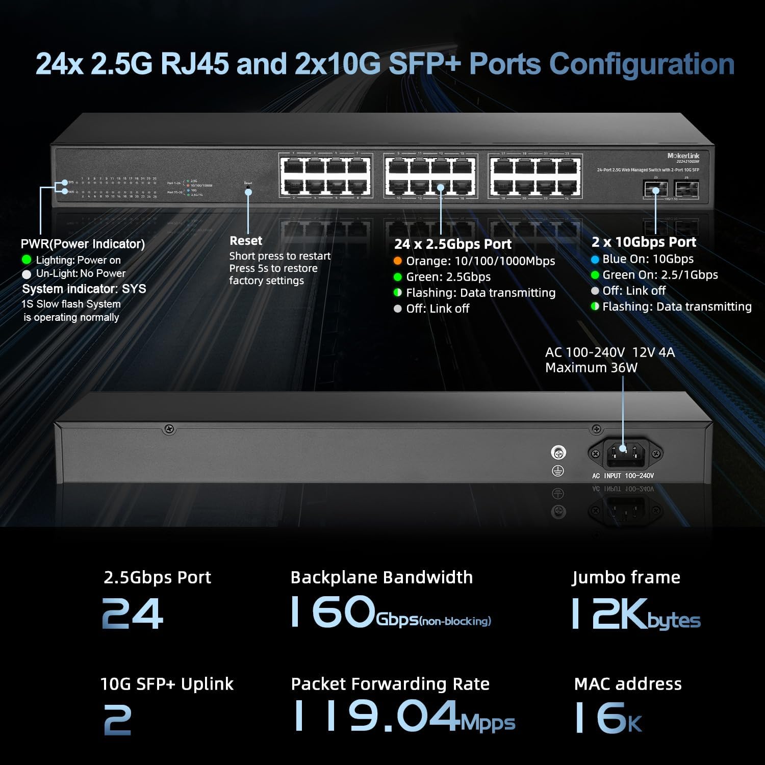
The front panel includes 24 RJ45 ports for 2.5G Ethernet connections, two SFP+ ports for 10G uplinks, and LED indicators for power, system status, and port activity. A reset button is also located on the front panel.
2.4 Rear Panel Layout

The rear panel of the switch features the AC power input connector.
3. Setup
3.1 Physical Installation
The switch can be placed on a desktop or mounted in a standard 19-inch equipment rack. Ensure adequate ventilation around the device.
- Desktop Placement: Place the switch on a flat, stable surface. Ensure there is sufficient space for air circulation.
- Rack Mounting: Attach the provided rackmount ears (if included) to the sides of the switch using the screws. Secure the switch into a standard 19-inch rack.

For optimal performance and longevity, avoid placing the switch in direct sunlight, near heat sources, or in areas with high humidity or dust.
3.2 Connecting Power
- Connect the power cord to the AC power input on the rear panel of the switch.
- Plug the other end of the power cord into a standard AC power outlet (100-240V AC, 50/60Hz).
- Verify that the PWR LED indicator on the front panel illuminates, indicating the switch is receiving power.
3.3 Connecting Network Devices
Use standard Ethernet cables (Cat5e, Cat6, or Cat6a for optimal 2.5G performance) to connect your network devices (e.g., computers, servers, NAS, Wi-Fi 6 APs) to the 2.5G RJ45 ports on the switch. For high-speed uplinks, insert compatible SFP+ modules into the 10G SFP+ ports and connect fiber optic cables.
The switch supports auto MDI/MDIX, so you can use either straight-through or crossover Ethernet cables. The ports also feature auto-negotiation for speed and duplex settings.
4. Operating Instructions
4.1 Accessing the Web Management Interface
The MokerLink switch is web-managed, allowing configuration through a standard web browser. Follow these steps to access the interface:
- Ensure your computer is connected to one of the switch's Ethernet ports.
- Configure your computer's IP address to be in the same subnet as the switch's default IP address (e.g., if the switch is 192.168.2.1, set your computer to 192.168.2.x with subnet mask 255.255.255.0).
- Open a web browser and enter the default IP address of the switch: 192.168.2.1
- When prompted, enter the default username and password:
- Username: admin
- Password: admin
- Upon successful login, you will see the switch's management dashboard.

It is highly recommended to change the default login credentials immediately after initial access for security purposes. Remember to save any configuration changes before exiting the interface or power cycling the device.
4.2 LED Indicators
The LED indicators on the front panel provide real-time status information:
- PWR (Power Indicator):
- Lighting On: Power is on.
- Un-Light: No power.
- SYS (System Indicator):
- Slow Flash: System is operating normally.
- Port LEDs (2.5Gbps Ports):
- Orange: 10/100/1000Mbps link.
- Green: 2.5Gbps link.
- Flashing: Data transmitting.
- Off: Link off.
- Port LEDs (10Gbps SFP+ Ports):
- Blue On: 10Gbps link.
- Green On: 2.5Gbps/1Gbps link.
- Flashing: Data transmitting.
- Off: Link off.
5. Advanced Features
The MokerLink managed switch offers a suite of Layer 2 features to optimize network performance and security.
5.1 VLAN (Virtual Local Area Network)
VLANs allow you to logically segment your network into separate broadcast domains, improving security and network efficiency. The switch supports 802.1Q Tag-based VLANs.

Refer to the web management interface for detailed VLAN configuration steps, including creating VLANs, assigning ports, and configuring PVIDs.
5.2 QoS (Quality of Service)
QoS prioritizes network traffic to ensure critical applications (e.g., VoIP, video conferencing) receive sufficient bandwidth, reducing latency and packet loss.

The web interface allows you to configure QoS policies based on port, 802.1p, or DSCP values.
5.3 LACP (Link Aggregation Control Protocol)
LACP allows you to group multiple physical links into a single logical link, increasing bandwidth and providing redundancy. This is useful for connecting to servers or other switches.

Configure LACP through the web management interface by selecting the ports to be aggregated and setting the appropriate parameters.
5.4 Loop Detection
Loop detection helps prevent network loops, which can cause broadcast storms and network instability. When a loop is detected, the switch can automatically disable the affected port to maintain network stability.

Enable and configure loop detection settings via the web management interface.
5.5 Other Layer 2 Features
The switch also supports other Layer 2 features including:
- IGMP Snooping: Optimizes multicast traffic delivery.
- Port Mirroring: Allows monitoring of network traffic by sending copies of packets to a designated port.
- STP/RSTP: Spanning Tree Protocol and Rapid Spanning Tree Protocol for loop prevention.
- MAC Address Table Management: Control and view MAC address entries.
- Jumbo Frame Support: Supports jumbo frames up to 12KB for increased data transfer efficiency.
6. Maintenance
6.1 Firmware Updates
Periodically check the MokerLink official website for firmware updates. Firmware updates can provide new features, performance improvements, and security enhancements. Follow the instructions provided with the firmware update package carefully.
6.2 Cleaning
To maintain optimal performance, keep the switch clean and free of dust. Use a soft, dry cloth to wipe the exterior. Do not use liquid or aerosol cleaners.
6.3 Environmental Considerations
The fanless design of this switch contributes to its quiet operation. Ensure the operating environment is within the recommended temperature and humidity ranges to prevent overheating and ensure stable performance.
7. Troubleshooting
7.1 No Power
- Ensure the power cord is securely connected to both the switch and a working power outlet.
- Verify the power outlet is functional by plugging in another device.
- Check the PWR LED on the front panel. If it is off, the switch is not receiving power.
7.2 No Link on a Port
- Ensure the Ethernet cable is securely connected to both the switch port and the connected device.
- Verify the cable is not damaged. Try a different cable.
- Check the link status LED for the specific port. If it's off, there's no link.
- Ensure the connected device is powered on and its network adapter is enabled.
- For SFP+ ports, ensure the SFP+ module is correctly inserted and compatible, and the fiber cable is properly connected.
7.3 Cannot Access Web Management Interface
- Verify your computer's IP address is in the same subnet as the switch's IP address (default: 192.168.2.x).
- Ensure you are using the correct IP address (default: 192.168.2.1).
- Confirm the correct username and password (default: admin/admin).
- Clear your browser's cache or try a different browser.
- Temporarily disable any firewall or antivirus software on your computer that might be blocking access.
7.4 Resetting to Factory Settings
If you encounter persistent issues or forget the login credentials, you can reset the switch to its factory default settings:
- With the switch powered on, locate the Reset button on the front panel.
- Use a paperclip or a similar pointed object to press and hold the Reset button for approximately 5 seconds.
- Release the button. The switch will reboot with factory default settings.
8. Specifications
| Feature | Description |
|---|---|
| Model | 24*2.5G Managed |
| Ports | 24x 2.5G Base-T RJ45, 2x 10G SFP+ |
| Standards | IEEE 802.3, 802.3u, 802.3ab, 802.3bz, 802.3ae, 802.3x, 802.1Q, 802.1p |
| Backplane Bandwidth | 160 Gbps |
| Packet Forwarding Rate | 119.04 Mpps |
| MAC Address Table | 16K |
| Jumbo Frame | 12 KB |
| Power Supply | AC 100-240V, 12V 4A (Max 36W) |
| Dimensions (L x W x H) | 440mm x 210mm x 44mm (17.32 x 8.27 x 1.73 inches) |
| Item Weight | 6.93 pounds (3.14 kg) |
| Case Material | Metal |
| Cooling | Fanless |
9. Warranty and Support
MokerLink products are covered by a limited warranty. Please refer to the warranty card included with your product or visit the official MokerLink website for detailed warranty terms and conditions.
For technical support, troubleshooting assistance, or product inquiries, please contact MokerLink customer support through their official channels. Contact information can typically be found on the MokerLink website or on the product packaging.


