PowMr POW-RELAB-5KU
PowMr 5000W 48V Hybrid Solar Inverter Instruction Manual
Model: POW-RELAB-5KU
1. Product Overview
The PowMr 5000W 48V to 110VAC Hybrid Solar Inverter is a robust off-grid solution designed for reliable power conversion. It integrates solar energy storage, mains charging, and AC sine wave output, making it suitable for various domestic and industrial applications. With a peak power of 15000W, it can handle high-power equipment startup needs. The low-frequency design with a toroidal transformer ensures stable and reliable operation.
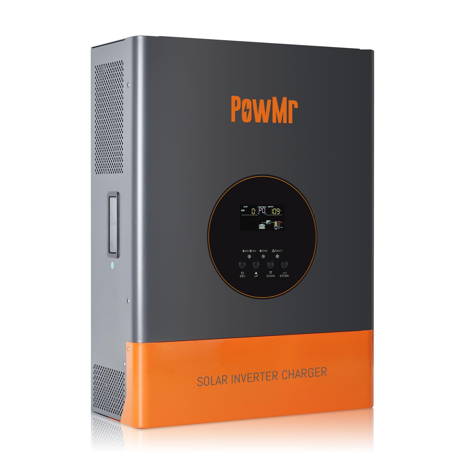
Figure 1: Front view of the PowMr 5000W Hybrid Solar Inverter.
2. Key Features
- Low Frequency Off-Grid Inverter: 5000W pure sine wave output with 3 times peak power (15000W) for powerful load capacity. Features a toroidal transformer for stability.
- Hybrid Solar Inverter: All-in-one design integrating solar energy storage, mains charging, and AC sine wave output. Converts DC 48V to AC 110V/120V.
- Advanced MPPT Charge Controller: Built-in 120A MPPT charge controller for efficient solar charging.
- Comprehensive Specifications: Rated Output Power: 5000W; Nominal DC Input Voltage: 48Vdc; Max. PV Array Power: 6400W; MPPT Input Voltage Range: 60~150Vdc; Max. PV Array Open Circuit Voltage: 150Vdc; Maximum AC Charging Current: 29A; Max. PV Charging Current: 120A; Efficiency: >98%.
- LCD Display & Real-Time Monitoring: LCD display and 3 LED indicators provide dynamic system data and operating status. Displays fault codes for easy troubleshooting.
- Multiple Charging & Output Modes: Supports 4 charging modes (Only Solar, Mains Priority, Solar Priority, Mains & Solar hybrid) and 2 output modes (Mains bypass, Inverter output) for uninterrupted power supply.
- Battery Compatibility: Compatible with various 48V batteries including AGM, Gel, Lead-acid, Lithium-ion, and LiFePO4. Includes built-in lithium activation and comprehensive battery protection.
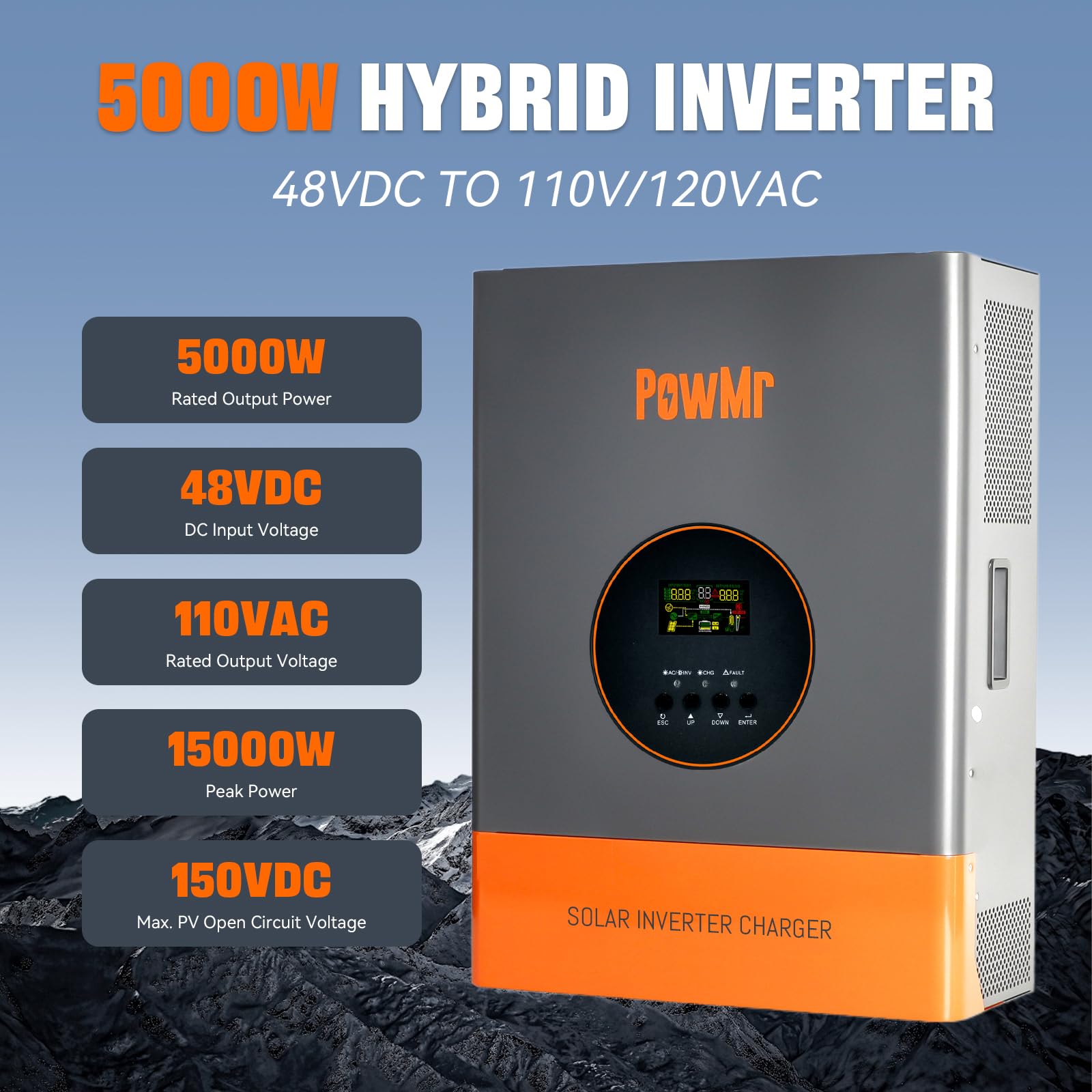
Figure 2: Key specifications of the 5000W Hybrid Inverter.
3. Setup & Installation
Proper installation is crucial for the safe and efficient operation of your PowMr Hybrid Solar Inverter. Please follow the guidelines below carefully.
3.1. Installation Video Guide
Video 1: Detailed installation guide for the PowMr 5000W/3000W 48V Hybrid Solar Inverter. This video demonstrates the physical setup and initial wiring steps.
3.2. Connection Diagram
The following diagram illustrates the typical connection setup for the inverter, including AC input, PV array, battery input, and AC output connections.

Figure 3: Inverter Connection Diagram. This diagram shows how to connect the inverter to the grid, solar panels, batteries, and loads.
3.3. Port Introduction
Familiarize yourself with the various ports and their functions on the inverter unit.
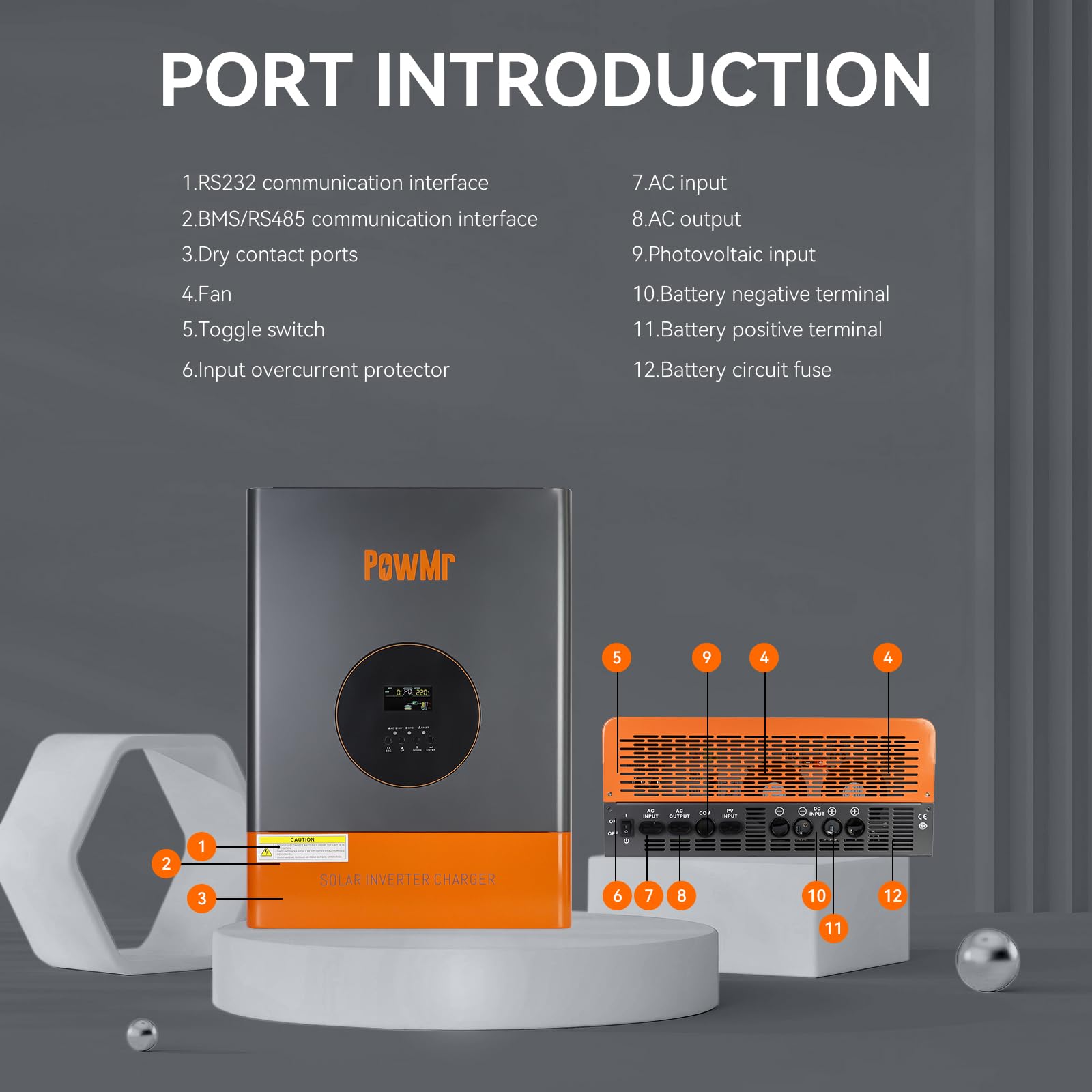
Figure 4: Port Introduction. Key ports include RS232/BMS communication, dry contact, fan, toggle switch, input overcurrent protector, AC input/output, photovoltaic input, battery terminals, and battery circuit fuse.
4. Configuration Settings
After powering on the inverter, press and hold the ENTER key for 10 seconds to access the settings mode. Use the UP and DOWN buttons to navigate and ENTER to confirm changes. Refer to the video guide for a visual demonstration of these settings.
4.1. Grid Input Voltage Range (#00)
Configures the AC input voltage range. Options include:
- Narrow Range (UPS Mode): Suitable for regions with stable voltage. Quickly disconnects to protect equipment if voltage exceeds set range.
- Wide Range (APL Mode): Accommodates greater input voltage fluctuations, ensuring continuous and stable power supply in areas with significant voltage variations. Prolonged exposure to large fluctuations may impact inverter and load lifespan.
4.2. Grid Frequency Range (#01)
Configures the AC frequency voltage range. Options include a wide range (40-65Hz) and a narrow range (45-65Hz).
4.3. Operating Mode (#02)
Configures the load output power priority:
- UTI Mode (Utility Priority): Utility grid is the primary power source. If utility is unavailable, solar and battery power are used.
- SOL Mode (Solar Priority): Solar power is the primary source. If solar power cannot meet load requirements, battery power supplements. If solar is unavailable, output switches to utility.
- SBU Mode (Inverter Priority): Solar and battery power are prioritized. Solar power is used first, with battery supplementing if necessary. If solar is unavailable, output switches to battery power. If battery voltage drops to undervoltage warning level, output switches to utility grid.
4.4. Charging Mode (#03)
Configures the charging source priority:
- CUT Mode (Utility Power Priority): Utility power primarily charges the battery, with solar simultaneously charging. If battery voltage falls below the set voltage (Setting 9), charging switches to utility. If battery voltage exceeds the value (Setting 10), it switches back to solar.
- CSO Mode (Solar Priority): Solar power primarily charges the battery. If battery voltage falls below the set voltage (Setting 9), charging switches to utility. If battery voltage exceeds the value (Setting 10), it switches back to solar.
- OSO Mode (Only Solar): Only solar power charges the battery.
4.5. Grid Charging Current Percentage (#04)
Configures the percentage of total charging current allocated to utility charging.
4.6. Solar Charging Current Percentage (#05)
Configures the percentage of total charging current allocated to solar charging.
4.7. Boost Charging Voltage (CV) (#06)
Configures the boost charging voltage, which should be set according to the battery manual.
4.8. Float Charging Voltage (#07)
Configures the float charging voltage, also referencing the battery manual.
4.9. Battery Discharge Cutoff Shutdown Voltage (#08)
Configures the battery discharge cut-off voltage to protect the battery from over-discharge. If the battery voltage falls below this value, the inverter will automatically shut down.
4.10. Enable Grid Charging Voltage (#09)
Configures the voltage at which the charging source switches to utility in CSO mode.
4.11. Exit Grid Charging Voltage (#10)
Configures the voltage at which the charging source switches back to solar in CSO mode.
4.12. Inverter Output Voltage (#11)
Configures the inverter output voltage, referencing the ranges for low and high voltage models displayed on the screen.
4.13. Grid Detection Speed (#12)
Configures the AC detection speed. Options include:
- HI (Fast): Quickly reacts to sudden voltage changes, protecting sensitive loads but may increase wear on the inverter due to frequent switching.
- IDE (Medium): Balances protection and device lifespan, suitable for general appliances and lighting.
- LO (Slow): Reduces wear but may not protect sensitive loads from sudden voltage spikes.
4.14. Inverter Output Frequency (#13)
Configures the inverter output frequency to either 50Hz or 60Hz.
4.15. Fault Restart Switch (#14)
Enables or disables the automatic restart function. If enabled, the inverter will attempt to restart three times after a short circuit or overload fault.
4.16. Backlight Control (#15)
Configures the backlight function with options for always on, always off, or delayed off (backlight turns off after one minute of inactivity).
4.17. Buzzer Control Switch (#16)
Enables or disables the buzzer alarm function. If enabled, the inverter will sound an alarm during faults.
4.18. Battery Under Voltage Alarm Switch (#17)
Enables or disables the low battery voltage alarm. It is recommended not to disable this to protect the battery from irreversible damage due to undervoltage or over-discharge.
4.19. Load Limitation (#18)
Used to enable or disable the battery undervoltage shutdown function. When enabled, if the battery voltage falls below the inverter's built-in preset threshold, the inverter will automatically shut down. It will remain off until it detects photovoltaic (PV) or AC input, at which point it will automatically restart. This undervoltage shutdown function provides a higher level of protection compared to the undervoltage cutoff voltage control. Under undervoltage cutoff protection, if the battery voltage drops below a certain threshold, the inverter will stop outputting to the load but will remain in standby mode, consuming a small amount of battery power. To prevent prolonged standby power consumption and to protect the battery, the undervoltage shutdown function will completely shut off the inverter when the battery voltage falls below the shutdown threshold, thereby halting all battery power consumption.
4.20. Unsupported Settings (#19, #21)
Settings 19 and 21 are not user-configurable.
4.21. Baud Rate (#20)
Configures the baud rate for communication between the inverter and external devices, with selectable baud rates shown on the screen.
4.22. Startup Battery Voltage (#22)
Configures the battery voltage required to manually start the inverter after an abnormal shutdown.
4.23. Undervoltage Shutdown Recovery Voltage (#23)
Configures the undervoltage recovery voltage, allowing the inverter to automatically restart when the battery voltage exceeds this value.
4.24. Battery Type (#24)
Configures the battery type, including user-defined options for ternary lithium battery, lithium iron phosphate battery, sealed lead-acid battery, GEL battery, and flooded lead-acid battery. If customizable, ternary lithium or lithium iron phosphate is selected, the charging parameters can be manually set. If lithium batteries with BMS communication are used, manual parameter setting is unnecessary.
4.25. BMS Function Switch (#25)
Enables or disables BMS communication. When BMS communication with lithium batteries is successful, settings 26 to 29 can be configured, and the inverter will use the SOC value as a reference for battery charging and discharging.
4.26. Undervoltage Shutdown SOC (#26)
Configures the SOC at which the inverter will shut down due to undervoltage.
4.27. Switch to Utility Mode SOC (#27)
Configures the SOC at which the operating mode switches to utility.
4.28. Switch to Inverter Mode SOC (#28)
Configures the SOC at which the operating mode switches to inverter priority.
4.29. Restart SOC (#29)
Configures the SOC required for normal operation after the inverter is turned on.
4.30. Restore Factory Settings (#30)
Allows for a one-click restore to factory settings.
4.31. ECO Energy Saving Mode (#ECO)
Enables or disables the energy-saving mode.
5. Operating Modes
The inverter supports various operating modes to optimize power flow based on availability and priority:
- Utility Priority (UTI): Grid power is the primary source for the load. Solar and battery power are used if the grid is unavailable.
- Solar Priority (SOL): Solar power is the primary source for the load. Battery power supplements if solar is insufficient. If solar is unavailable, the output switches to utility.
- Inverter Priority (SBU): Solar and battery power are prioritized. Solar is used first, then battery. If both are insufficient or battery voltage is low, the output switches to utility.

Figure 5: Visual representation of the three primary output modes.
6. Charging Modes
The inverter offers flexible charging options to manage battery health and energy sources:
- Mains Priority (CUT): Utility power is the primary source for charging the battery, supplemented by solar.
- Solar Priority (CSO): Solar power is the primary source for charging the battery. Utility power is used if solar is insufficient.
- Only Solar (OSO): Only solar power is used to charge the battery.

Figure 6: Visual representation of the three primary charging modes.
7. Protection Functions
The PowMr Hybrid Solar Inverter is equipped with multiple protection features to ensure safe and reliable operation of both the inverter and connected devices.

Figure 7: Multi-Protection Functions. These include protection against overload, charge short circuits, AC reverse polarity, short circuits, bypass overcurrent, battery overvoltage, battery low voltage, and parallel connection errors.

Figure 8: 360 Degree Protection. This encompasses short circuit protection, overcurrent protection, overvoltage protection, undervoltage protection, overload protection, backfill protection, over-temperature protection, and overcharge protection.
8. Technical Specifications
| Specification | Value |
|---|---|
| Rated Output Power | 5000W |
| Peak Power | 15000W |
| Rated Output Voltage Range | 110Vac±10% |
| Nominal DC Input Voltage | 48Vdc |
| Max. PV Array Power | 6400W |
| MPPT Input Voltage Range | 60~150Vdc |
| Max. PV Array Open Circuit Voltage | 150Vdc |
| Maximum AC Charging Current | 29A |
| Max. PV Charging Current | 120A |
| Efficiency | >98% |
| Product Dimensions | 15.7 x 7.87 x 21.45 inches |
| Item Weight | 60.9 pounds |
| Model Name | POW-RELAB-5KU |

Figure 9: Detailed wiring diagram and technical specifications.
9. Maintenance
Regular maintenance ensures the longevity and optimal performance of your inverter. Perform the following checks periodically:
- Keep the inverter's ventilation openings clear of dust and debris to ensure proper airflow and prevent overheating.
- Inspect all wiring connections for tightness and signs of corrosion. Loose connections can lead to power loss or safety hazards.
- Check the battery terminals for cleanliness and secure connections. Ensure batteries are maintained according to their manufacturer's guidelines.
- Monitor the LCD display for any fault codes or unusual operating conditions. Address any warnings promptly.
- Ensure the inverter is installed in a dry, well-ventilated area, away from direct sunlight, heat sources, and flammable materials.
10. Troubleshooting
The inverter's LCD display provides fault codes to assist in diagnosing issues. Refer to the specific fault code displayed on the screen and consult the comprehensive troubleshooting section in the full product manual for detailed solutions. Common issues and their indicators include:
- Overload: Indicated by a specific fault code and potentially an alarm. Reduce connected load.
- Battery Undervoltage: The inverter may shut down or switch modes. Check battery charge level and connections.
- Over-temperature: Ensure proper ventilation and clear any obstructions around the inverter's cooling fins.
- Short Circuit: The inverter will shut down to protect itself. Identify and resolve the short circuit in the wiring or connected load.
For persistent issues or fault codes not listed, contact PowMr customer support.
11. Warranty and Support
PowMr products are backed by a manufacturer's warranty. For specific warranty terms and conditions, please refer to the warranty card included with your product or visit the official PowMr website. For technical support, troubleshooting assistance, or spare parts, please contact PowMr customer service through the contact information provided in your product packaging or on the official website.
When contacting support, please have your product model (POW-RELAB-5KU) and serial number ready to expedite the process.
Ask a question about this manual
Ask about setup, troubleshooting, compatibility, parts, safety, or missing instructions. Manuals+ will review the question and use this page’s manual context to help answer it.