1. Introduction
This manual provides detailed instructions for the installation, operation, and maintenance of your PowMr 3000W 24V Hybrid Solar Inverter. This low-frequency pure sine wave inverter offers a powerful load capacity with a peak power of 9000W, suitable for various domestic and industrial applications. It features a built-in 38A AC charger and supports multiple battery types, including Flooded, LiCoMnNiO2, LiFePO4, AGM, and Gel.
Key features include:
- 3000W low-frequency pure sine wave output (9000W peak)
- Max PV input power: 1600W 105V; Max PV input: 60A
- MPPT input voltage range: 30-105VDC
- Maximum AC input current: 38A
- Output frequency: 50Hz/60Hz; Output voltage: 110Vac±10%
- Compatible with various 24V battery types
- Multiple protection functions for enhanced safety and longevity
2. Safety Information
Please read all instructions and warnings carefully before installation and operation. Failure to follow these instructions may result in electric shock, fire, or severe injury. Keep this manual for future reference.
- Ensure all wiring is performed by qualified personnel.
- Do not expose the inverter to rain, snow, or liquids.
- Ensure proper ventilation around the inverter to prevent overheating.
- Do not disassemble or attempt to repair the inverter yourself. Refer to qualified service personnel.
- Always disconnect all power sources (solar, battery, AC) before performing any maintenance or wiring.

Figure 2.1: Multi-Protection Functions of the PowMr Inverter
The inverter is equipped with multiple protection functions including overload, charge short, AC reverse, short-circuit, bypass overcurrent, battery overvoltage, battery low voltage, and parallel connection error protection to ensure safe and reliable operation.
3. What's in the Box
Upon unpacking, please verify that all items are present and undamaged:
- PowMr 3000W 24V Hybrid Solar Inverter
- Battery AC Charger
- User Manual
4. Product Overview
The PowMr Hybrid Solar Inverter is designed for off-grid power supply, integrating a low-frequency pure sine wave inverter with a robust MPPT solar charge controller and an AC battery charger. Its toroidal transformer design ensures stability and reliability.

Figure 4.1: PowMr 3000W 24V Hybrid Solar Inverter

Figure 4.2: Key Specifications of the Hybrid Inverter
5. Installation and Connections
Proper installation is crucial for the safe and efficient operation of your inverter. Follow the connection diagram carefully.

Figure 5.1: Port Introduction
- RS232 communication interface: For data communication.
- BMS/RS485 communication interface: For Battery Management System communication.
- Dry contact ports: For external control signals.
- Fan: For cooling.
- Toggle switch: Main power switch.
- Input overcurrent protector: Protects against excessive input current.
- AC input: Connects to utility grid or generator.
- AC output: Connects to household appliances.
- Photovoltaic input: Connects to solar panels.
- Battery negative terminal: Connects to battery bank negative.
- Battery positive terminal: Connects to battery bank positive.
- Battery circuit fuse: Protects the battery circuit.
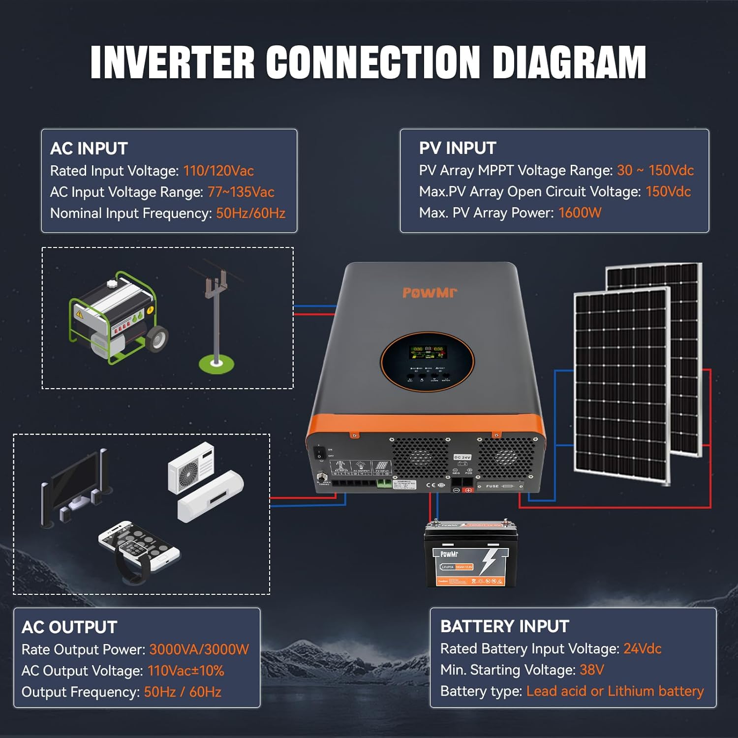
Figure 5.2: Inverter Connection Diagram
Ensure all connections are secure and correctly polarized. Refer to the diagram for proper wiring of AC input, PV input, battery input, and AC output.

Figure 5.3: Supported Battery Types and Max Currents
6. Operating Instructions: Settings Configuration
After turning on the inverter, press and hold the ENTER key for 10 seconds to enter the settings mode. Use the UP and DOWN buttons to navigate and ENTER to confirm.
Video 6.1: PowMr Hybrid Solar Inverter Settings Configuration Guide. This video demonstrates how to access and configure various settings on the inverter's display panel.
6.1. Grid Input Voltage Range (#00)
Configures the AC input voltage range. Choose between a wide or narrow range. The wide range accommodates greater input voltage fluctuations, ensuring stable power supply in areas with significant voltage variations. The narrow range quickly disconnects to protect equipment if voltage exceeds the set range, suitable for regions with stable voltage. Prolonged exposure to large fluctuations may impact inverter lifespan in narrow range.
6.2. Grid Frequency Range (#01)
Configures the AC frequency voltage range. Options include a wide range (40-65Hz) and a narrow range (45-65Hz).
6.3. Operating Mode (#02)
Configures the operation mode or load output power priority:
- UTI Mode (Utility Priority): The utility grid is the primary power source. If utility power is unavailable, solar and battery power will be used.
- SOL Mode (Solar Priority): Solar power is the primary source. If solar power cannot meet the load's requirements, battery power will supplement. If solar power is unavailable, the output switches to the utility grid, even if the battery is sufficiently charged.
- SBU Mode (Inverter Priority): Solar and battery power are prioritized. Solar power is used first, with the battery supplementing if necessary. When solar power is unavailable, the output switches to battery power. If battery voltage drops to the undervoltage warning level, the output switches to the utility grid.
6.4. Charging Mode (#03)
Configures the charging mode:
- CUT Mode (Utility Power Priority): Utility power primarily charges the battery, with solar simultaneously charging the battery. When battery voltage falls below the voltage set in Setting 9, the charging source switches to utility. When battery voltage exceeds the value set in Setting 10, it switches back to solar.
- CSO Mode (Solar Priority): Solar power primarily charges the battery.
- OSO Mode (Only Solar Mode): Only solar power charges the battery.
6.5. Grid Charging Current Percentage (#04)
Configures the percentage of total charging current allocated to utility charging.
6.6. Solar Charging Current Percentage (#05)
Configures the percentage of total charging current allocated to solar charging.
6.7. Boost Charging Voltage (CV) (#06)
Configures the boost charging voltage, which should be set according to the battery manual.
6.8. Float Charging Voltage (#07)
Configures the float charging voltage, also referencing the battery manual.
6.9. Battery Discharge Cutoff Shutdown Voltage (#08)
Configures the battery discharge cut-off voltage to protect the battery from over-discharge. If the battery voltage falls below this value, the inverter will automatically shut down.
6.10. Enable Grid Charging Voltage (#09)
Configures the voltage at which the charging source switches to utility in CSO mode.
6.11. Exit Grid Charging Voltage (#10)
Configures the voltage at which the charging source switches back to solar in CSO mode.
6.12. Inverter Output Voltage (#11)
Configures the inverter output voltage, referencing the ranges for low and high voltage models displayed on the screen.
6.13. Grid Detection Speed (#12)
Configures the AC detection speed with options for Fast (HI), Medium (IDE), and Slow (LO).
- Fast response: Quickly reacts to sudden voltage changes, protecting sensitive loads but may increase wear on the inverter due to frequent switching.
- Slow response: Reduces wear but may not protect sensitive loads from sudden voltage spikes.
- Medium response: Balances protection and device lifespan, suitable for general appliances and lighting.
6.14. Inverter Output Frequency (#13)
Configures the inverter output frequency to either 50Hz or 60Hz.
6.15. Fault Restart Switch (#14)
Enables or disables the automatic restart function. If enabled, the inverter will attempt to restart three times after a short circuit or overload fault.
6.16. Backlight Control (#15)
Configures the backlight function with options for always on, always off, or delayed off (backlight turns off after one minute of inactivity).
6.17. Buzzer Control Switch (#16)
Enables or disables the buzzer alarm function. If enabled, the inverter will sound an alarm during faults.
6.18. Battery Under Voltage Alarm Switch (#17)
Enables or disables the low battery voltage alarm. It is recommended not to disable this to protect the battery from irreversible damage due to undervoltage or over-discharge.
6.19. Load Limitation (#18)
Used to enable or disable the battery undervoltage shutdown function. When enabled, if the battery voltage falls below the inverter's built-in preset threshold, the inverter will automatically shut down. It will remain off until it detects photovoltaic (PV) or AC input, at which point it will automatically restart. This undervoltage shutdown function provides a higher level of protection compared to the undervoltage cutoff voltage control. Under undervoltage cutoff protection, if the battery voltage drops below a certain threshold, the inverter will stop outputting to the load but will remain in standby mode, consuming a small amount of battery power. To prevent prolonged standby power consumption and to protect the battery, the undervoltage shutdown function will completely shut off the inverter when the battery voltage falls below the shutdown threshold, thereby halting all battery power consumption.
6.20. Unsupported Settings (#19)
Setting 19 is not user-configurable.
6.21. Baud Rate (#20)
Configures the baud rate for communication between the inverter and external devices, with selectable baud rates shown on the screen.
6.22. Unsupported Settings (#21)
Setting 21 shows the inverter output voltage and is not user-configurable.
6.23. Startup Battery Voltage (#22)
Configures the battery voltage required to manually start the inverter after an abnormal shutdown.
6.24. Undervoltage Shutdown Recovery Voltage (#23)
Configures the undervoltage recovery voltage, allowing the inverter to automatically restart when the battery voltage exceeds this value.
6.25. Battery Type (#24)
Configures the battery type, including user-defined options for Ternary Lithium Battery, Lithium Iron Phosphate Battery, Sealed Lead-Acid Battery, GEL Battery, and Flooded Lead-Acid Battery. If customizable, Ternary Lithium or Lithium Iron Phosphate is selected, the charging parameters can be manually set. If lithium batteries with BMS communication are used, manual parameter setting is unnecessary.
6.26. BMS Function Switch (#25)
Enables or disables BMS communication. When BMS communication with lithium batteries is successful, settings 26 to 29 can be configured, and the inverter will use the SOC value as a reference for battery charging and discharging.
6.27. Undervoltage Shutdown SOC (#26)
Configures the SOC at which the inverter will shut down due to undervoltage.
6.28. Switch to Utility Mode SOC (#27)
Configures the SOC at which the operating mode switches to utility.
6.29. Switch to Inverter Mode SOC (#28)
Configures the SOC at which the operating mode switches to inverter priority.
6.30. Restart SOC (#29)
Configures the SOC required for normal operation after the inverter is turned on.
6.31. Restore Factory Settings (#30)
Allows for a one-click restore to factory settings.
6.32. ECO Energy Saving Mode
Enables or disables the energy-saving mode.
7. Maintenance
Regular maintenance ensures the longevity and optimal performance of your inverter.
- Keep the inverter clean and free from dust and debris.
- Ensure proper ventilation and clear any obstructions from the cooling fans.
- Periodically check all electrical connections for tightness and signs of corrosion.
- Monitor the inverter's display for any error codes or warnings.
- Inspect battery terminals for corrosion and ensure they are clean and tight.
8. Troubleshooting
If you encounter issues with your inverter, refer to the following general troubleshooting steps. For complex problems, contact customer support.
- No Power: Check all power connections (AC input, battery, solar). Ensure the main switch is ON. Verify battery voltage is within operating range.
- No Output: Check for overload conditions. Reduce load if necessary. Check for short circuits on the output. Verify operating mode settings.
- Alarm Sounding: Refer to the display for specific error codes. Common alarms include overvoltage, undervoltage, overload, and over-temperature. Address the underlying cause as indicated by the error code.
- Battery Not Charging: Check solar panel connections and output. Verify AC input is present if utility charging is enabled. Check charging mode settings.
9. Specifications
| Feature | Specification |
|---|---|
| Product Dimensions | 12 x 5 x 18 inches |
| Item Weight | 41.8 pounds |
| Item Model Number | POW-RELAB-3KU |
| Rated Output Power | 3000W |
| Peak Power | 9000W |
| Max PV Input Power | 1600W 105V |
| Max PV Input Current | 60A |
| MPPT Input Voltage Range | 30-105VDC |
| Maximum AC Input Current | 38A |
| Output Frequency | 50Hz/60Hz |
| Output Voltage | 110Vac±10% |
| Power Source | Solar Powered |
| Recommended Uses | Off-grid power supply |
10. Warranty and Support
For warranty information, technical support, or service inquiries, please refer to the contact details provided with your purchase documentation or visit the official PowMr website. Keep your purchase receipt as proof of purchase for warranty claims.


