1. Introduction
This manual provides essential instructions for the installation, operation, and maintenance of your Luejnbogty 60V 50A Brushless Controller and 36V-60V LCD Display Dashboard Kit. This kit is designed for use with electric scooters and e-bikes, offering precise control and clear display of operational parameters. Please read this manual thoroughly before installation and use to ensure proper function and safety.
2. Product Overview
The Luejnbogty controller and display kit is engineered for robust performance and ease of integration. It includes the following main components:
- LCD Display Dashboard: Provides real-time information such as speed, battery level, and mode.
- Two 60V 50A Brushless Controllers: Designed for dual motor applications, ensuring efficient power delivery.
- Associated Wiring Harnesses: For connecting the display, controllers, and motors.
Key features of this product include:
- High-quality, durable construction using metal and plastic components.
- Designed for easy and secure installation without causing damage to the scooter or e-bike frame.
- Compact size and lightweight design to minimize additional burden on the vehicle.
- Adjustable voltage range for the LCD display (36V-60V).

Figure 2.1: Complete Luejnbogty 60V 50A Brushless Controller and 36V-60V LCD Display Dashboard Kit. This image shows the LCD display unit, two brushless controllers, and the accompanying wiring harnesses.
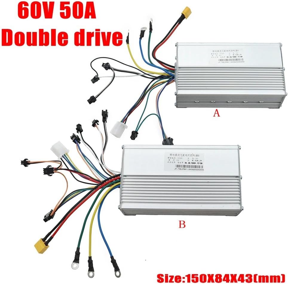
Figure 2.2: Two 60V 50A Brushless Controllers (labeled A and B) with their respective wiring. The image also indicates the controller dimensions as 150x84x43mm.
3. Safety Information
Adherence to safety guidelines is crucial during installation and operation. Failure to do so may result in injury or damage to the product or vehicle.
- Professional Installation Recommended: Due to the electrical nature of this product, professional installation by a qualified technician is highly recommended.
- Power Disconnection: Always disconnect the vehicle's power source before attempting any installation, maintenance, or repair.
- Voltage Compatibility: Ensure that your vehicle's battery voltage is compatible with the specified operating range of 36V-60V for the display and 60V for the controllers.
- Wiring: Double-check all wiring connections for proper polarity and secure fitment. Loose connections can lead to malfunctions or electrical hazards.
- Environmental Conditions: Avoid exposing the components to extreme temperatures, moisture, or corrosive environments.
4. Setup and Installation
This section outlines the general steps for installing the controller and display kit. Specific wiring diagrams for your particular scooter or e-bike model may be required and are not included in this manual.
4.1 Component Identification
- LCD Display: Typically mounts on the handlebar.
- Brushless Controllers: These are the rectangular metal units. For dual motor setups, one controller connects to each motor.
- Wiring Harnesses: Various connectors for power, motor phases, hall sensors, throttle, brakes, and display communication.

Figure 4.1: Close-up view of the LCD Display Dashboard unit, showing the screen, mode button, and power button.
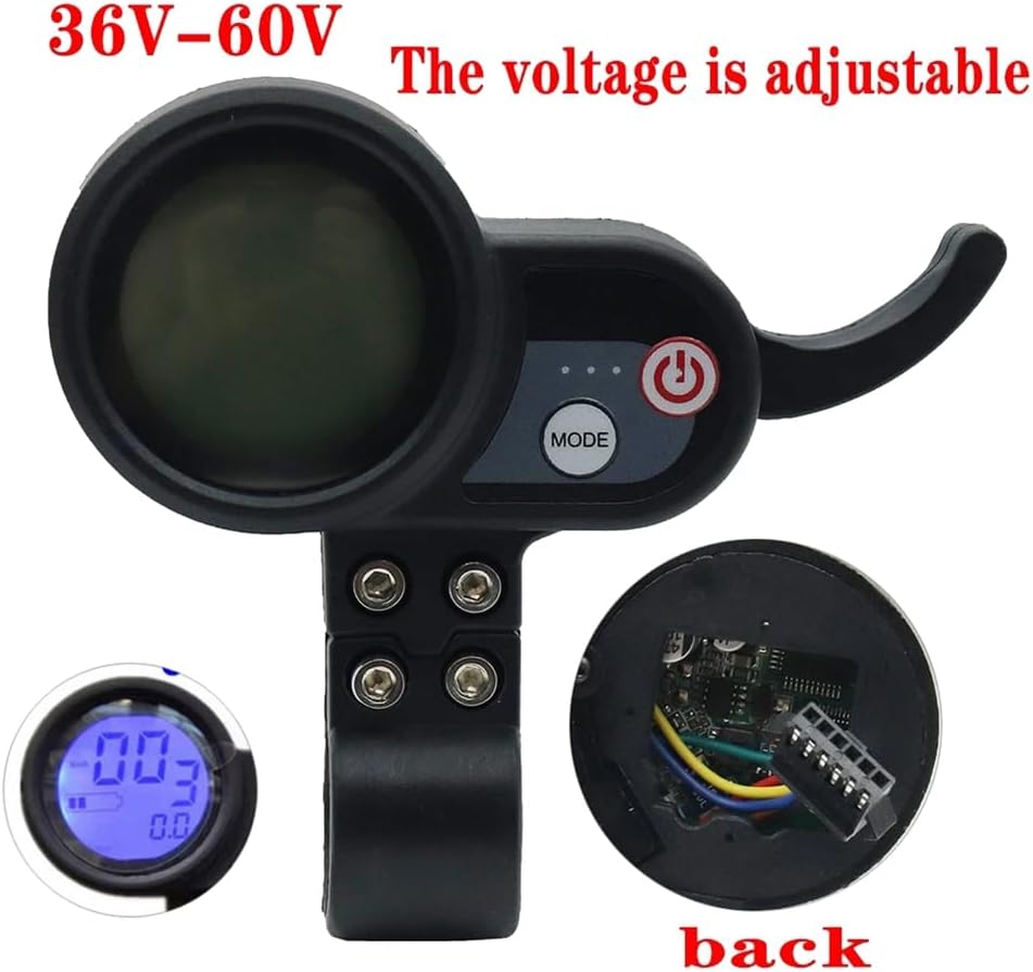
Figure 4.2: Rear view of the LCD Display Dashboard, illustrating the internal wiring connections. This display supports a voltage range of 36V-60V.
4.2 Installation Steps
- Mount the LCD Display: Securely attach the LCD display unit to the handlebar using the provided clamp and screws. Ensure it is positioned for easy viewing and access to buttons.
- Mount the Controllers: Find a suitable, protected location on your vehicle for the two brushless controllers. Ensure they are securely fastened and have adequate ventilation.
- Connect Power: Connect the main power wires from your vehicle's battery to the power input of each controller. Pay close attention to positive and negative terminals.
- Connect Motors: Connect the phase wires (usually three thick wires) and Hall sensor wires (usually five thin wires) from each motor to its respective controller. Match colors carefully.
- Connect Display: Connect the communication cable from the LCD display to the designated port on one of the controllers (typically the main controller).
- Connect Peripherals: Connect other peripherals such as the throttle, brake levers (if they have cut-off switches), and any other accessories to the appropriate ports on the controllers.
- Secure Wiring: Route and secure all wiring to prevent snagging, pinching, or damage during operation. Use zip ties or cable wraps as needed.
- Initial Test: Before full operation, perform a low-power test to ensure all components are functioning correctly. Check for any unusual noises or behavior.
5. Operating Instructions
Once installed, the system is ready for operation. Familiarize yourself with the LCD display and controller functions.
5.1 Power On/Off
- Power On: Press and hold the power button on the LCD display unit until the screen illuminates.
- Power Off: Press and hold the power button again until the display turns off.
5.2 LCD Display Functions
The LCD display provides critical information and allows for mode selection.
- Speed Display: Shows current speed (e.g., km/h or mph).
- Battery Level Indicator: Displays the remaining battery charge.
- Mode Selection: Use the 'MODE' button to cycle through different riding modes or display parameters (e.g., Odometer, Trip Distance, Voltage).
- Voltage Adjustment: The display supports a voltage range of 36V-60V. Specific instructions for adjusting or confirming the voltage setting may be available through the display's menu system. Refer to the display's dedicated manual if available for detailed parameter settings.
6. Maintenance
Regular maintenance helps ensure the longevity and reliable performance of your controller and display kit.
- Cleaning: Keep the LCD display and controllers clean. Use a soft, dry cloth to wipe away dust and dirt. Avoid using harsh chemicals or abrasive materials.
- Connection Inspection: Periodically check all electrical connections for tightness and signs of corrosion or wear. Re-secure any loose connections.
- Cable Integrity: Inspect all cables and wiring for cuts, fraying, or damage. Replace damaged cables immediately to prevent electrical shorts.
- Environmental Protection: While the components are designed for outdoor use, prolonged exposure to heavy rain or extreme temperatures should be avoided. Consider additional protective measures if operating in harsh conditions.
7. Troubleshooting
This section addresses common issues you might encounter. If problems persist, consult a professional technician.
7.1 Display Not Powering On
- Check Battery: Ensure the vehicle's battery is charged and properly connected.
- Check Power Connections: Verify that the power wires to the controllers and the display's communication cable are securely connected.
- Inspect Wiring: Look for any visible damage to the wiring that might prevent power flow.
7.2 Motors Not Responding
- Check Throttle: Ensure the throttle is correctly connected and functioning.
- Verify Motor Connections: Confirm that the phase wires and Hall sensor wires from the motors are correctly and securely connected to the controllers.
- Controller Status: Check if the controllers are receiving power and if there are any diagnostic indicators (if applicable).
- Brake Cut-off: If your brake levers have cut-off switches, ensure they are not engaged, as this will prevent motor operation.
7.3 Inaccurate Display Readings
- Check Connections: Ensure the display's communication cable is firmly connected to the controller.
- Voltage Setting: Verify that the display's voltage setting matches your battery's voltage.
8. Specifications
| Feature | Specification |
|---|---|
| Brand | Luejnbogty |
| Model | 60V 50A Brushless Controller and 36V-60V LCD Display Dashboard Kit |
| ASIN | B0D144P9ZM |
| Controller Voltage | 60V |
| Controller Current | 50A |
| Display Voltage Range | 36V-60V |
| Package Contents | 1 x LCD Display, 2 x Brushless Controller |
| Material | Metal + Plastic |
| Color | Black + Silver |
| Controller Dimensions (approx.) | 150mm x 84mm x 43mm |
| Date First Available | May 20, 2024 |
9. Warranty and Support
Specific warranty information for this product is not provided in the available product details. For any technical support, warranty claims, or further assistance, please contact the seller or manufacturer directly through your purchase platform.