FRPKPNOX TOQ3-4P/125
FRPKPNOX TOQ3-4P/125 Automatic Transfer Switch Instruction Manual
Model: TOQ3-4P/125 | Brand: FRPKPNOX
1. Introduction
This manual provides essential information for the safe and effective installation, operation, and maintenance of the FRPKPNOX TOQ3-4P/125 Automatic Transfer Switch (ATS). This device is designed to automatically switch between a normal power source and a reserve power source, ensuring continuous power supply to critical loads.
The TOQ3 is a terminal type automatic transfer device suitable for 3-phase, 4-wire (or 1-phase, 1-wire) dual power grids with AC 50/60Hz, rated voltage 400V/230V, and rated current up to 125A. It conforms to IEC60947-6-1 and GB/T14048.11 standards.
2. Safety Information
WARNING: Installation and maintenance should only be performed by qualified electrical personnel. Failure to follow these instructions may result in serious injury or death.
- Always disconnect all power sources before installing or servicing the ATS.
- Ensure proper grounding of the device.
- Verify all wiring connections are secure and correct according to the wiring diagram.
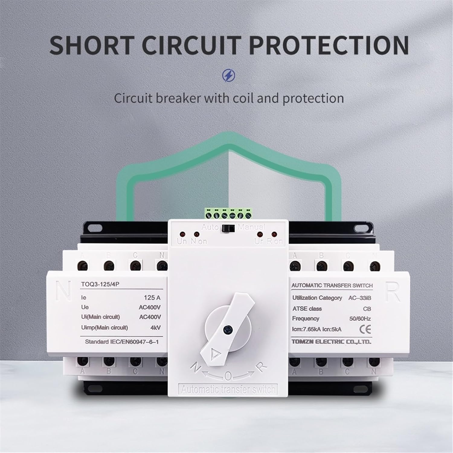
- The 125A ATS does not include overcurrent or short-circuit protection. Additional protective devices must be installed upstream.
- The power supply will be interrupted for less than 4 seconds during switching operations.
3. Product Specifications
| Parameter | Value |
|---|---|
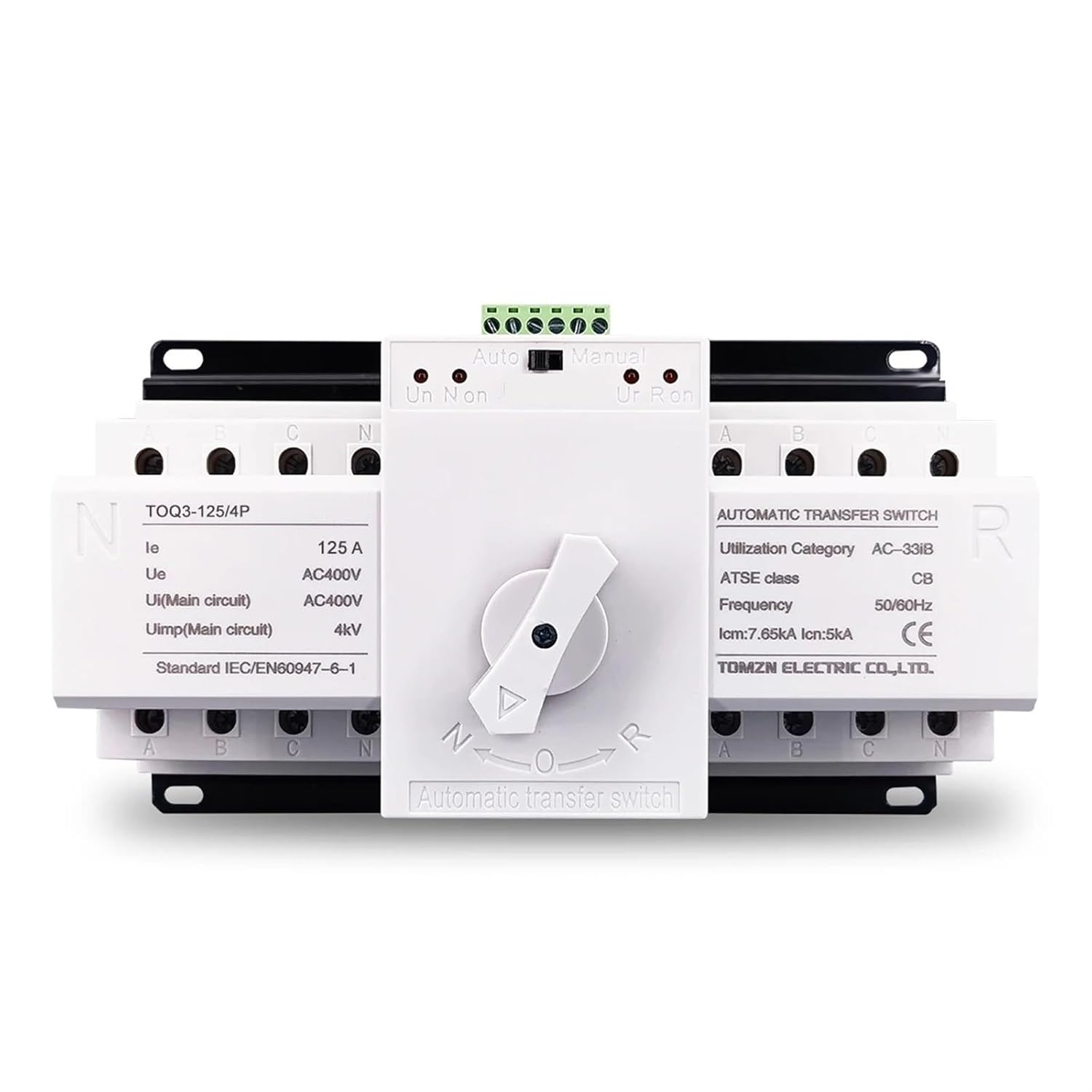
| Model | TOQ3-4P/125 |
| Rated Current (Ie) | 125 A |
| Rated Voltage (Ue) | AC400V (3-phase), AC230V (1-phase) |
| Rated Impulse Withstand Voltage (Uimp) | 4kV (Main circuit) |
| Frequency | 50/60Hz |
| Utilization Category | AC-33iB |
| ATSE Class | CB |
| Rated Short-Circuit Making Capacity (Icm) | 7.85kA |
| Rated Short-Circuit Breaking Capacity (Icn) | 5kA |
| Standard | IEC/EN60947-6-1 |
| Switching Time | < 4 seconds |
4. Installation
4.1 Mounting
The TOQ3-4P/125 ATS is designed for DIN rail mounting or screw mounting within an electrical enclosure. Ensure adequate ventilation and clearance around the device.
4.2 Wiring Diagram
Refer to the following diagram for proper wiring connections. The ATS supports both common power supply (Normal) and backup power (Reserve) inputs, connecting to a single load output.
- Connect the Normal power source (e.g., city power) to the terminals labeled 'N' on the left side of the switch.
- Connect the Reserve power source (e.g., generator) to the terminals labeled 'R' on the right side of the switch.
- Connect the load to the output terminals at the bottom of the switch.
- Ensure correct phase (L1, L2, L3) and neutral (N) connections for both power sources and the load.
- The control circuit terminals (top green block) are for automatic/manual mode selection and status indication.
5. Operation
5.1 Operating Modes
The ATS has two operating modes: Automatic and Manual.
- Automatic Mode:
Press the button to "Automatic". In this mode, the switch will automatically transfer between Normal power and Reserve power based on availability. The switch prioritizes Normal power. If Normal power is present, the switch will connect to Normal power. If Normal power fails and Reserve power is available, the switch will automatically transfer to Reserve power. The ATS only tests for loss of voltage or loss of phase on Normal Phase A and Reserve Phase A.
- Manual Mode:
Press the button to "Manual". In this mode, you must manually operate the central rotary switch to select between Normal (N) and Reserve (R) power sources. The switch will remain in the selected position until manually changed.
5.2 Power Transfer Logic
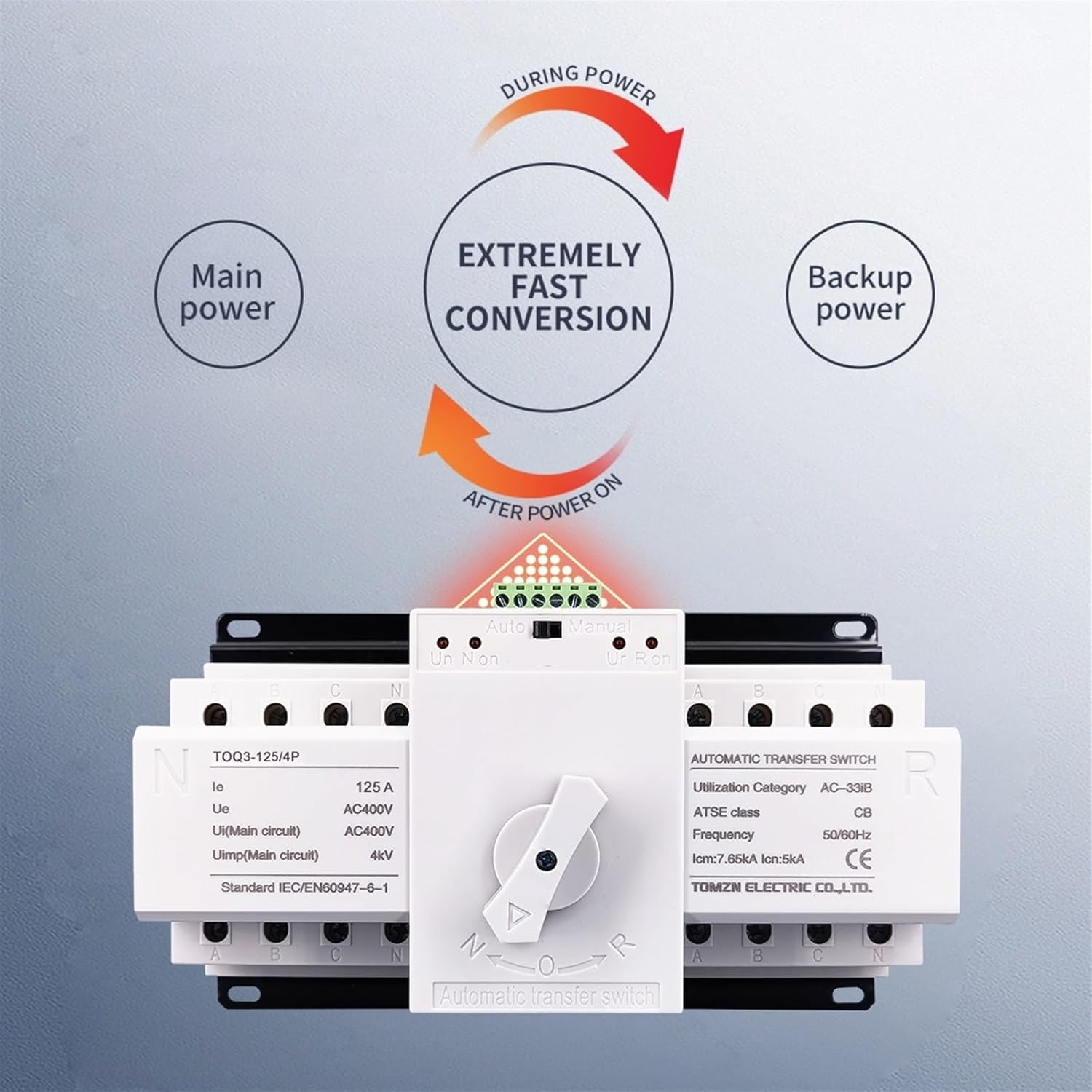
- The ATS is designed for extremely fast conversion, typically less than 4 seconds.
- The switch itself does not turn on or turn off the generator. It only transfers the load between available power sources.
6. Maintenance
Regular inspection and maintenance are crucial for the reliable operation of the ATS.
- Visual Inspection: Periodically check for any signs of physical damage, loose connections, or overheating.
- Cleaning: Ensure the device is free from dust and debris. Use a dry, soft cloth for cleaning. Do not use liquids.
- Connection Check: Verify that all terminal connections are tight and secure.
- Functional Test: Periodically test the automatic transfer function by simulating a power failure on the Normal source (if safe to do so and with proper precautions).
Note: All maintenance procedures should be performed by qualified personnel with power disconnected.
7. Troubleshooting
| Problem | Possible Cause | Solution |
|---|---|---|
| ATS does not transfer automatically. |
|
|
| No power to load after transfer. |
|
|
| ATS makes clicking sounds but doesn't switch. |
|
|
If problems persist after attempting these solutions, contact qualified service personnel.
8. Warranty and Support
For warranty information and technical support, please refer to the documentation provided with your purchase or contact FRPKPNOX customer service. Keep your purchase receipt for warranty claims.
Ask a question about this manual
Ask about setup, troubleshooting, compatibility, parts, safety, or missing instructions. Manuals+ will review the question and use this page’s manual context to help answer it.