1. Introduction
This manual provides comprehensive instructions for the SPARKHOBBY BZGNSS series of GPS positioning modules, including models BZ-121, BZ-181, and BZ-251. These modules are designed for high-precision positioning in various applications, particularly for FPV (First Person View) and fixed-wing drones. Please read this manual thoroughly before installation and operation to ensure proper use and optimal performance.
2. Safety Information
Devices and accessories are not toys. Do not allow young children to play with the equipment as they may injure themselves, others or damage the equipment. Keep the device and all its parts and accessories out of reach of young children.
Always handle the module with care to prevent damage to sensitive electronic components. Ensure proper power supply and wiring connections to avoid short circuits or malfunction. Operate the module within its specified temperature ranges.
3. Product Overview
The BZGNSS GPS positioning modules are advanced navigation devices featuring the M10050 (Ten Generation) chip, offering multi-constellation support for GPS, GLONASS, BDS, GALILEO, SBAS, and QZSS. They provide fast star acquisition, high accuracy, and dual protocol output (NMEA/UBLOX), making them versatile for integration with various flight controllers like F4 and F7.
Key Features:
- Multi-Constellation Support: Compatible with GPS, GLONASS, BDS, GALILEO, SBAS, QZSS for enhanced positioning accuracy.
- Dual Protocol Output: Supports both NMEA and UBLOX protocols for broad compatibility.
- High Precision: Achieves 2D ACC 1.5m horizontal positioning accuracy in open air.
- Fast Star Acquisition: Designed for quick and efficient satellite lock.
- Compact and Lightweight: Optimized for integration into RC airplanes and FPV fixed-wing aircraft.
- Ceramic Antenna: Features an ultrathin ceramic antenna with oil spraying process to prevent scratching and oxidation.

Image 3.1: SPARKHOBBY BZGNSS BZ-181 GPS Module with its connecting cable.
4. Models and Specifications
The BZGNSS series offers three distinct models: BZ-121, BZ-181, and BZ-251, each with specific dimensions and interface options to suit various integration needs.
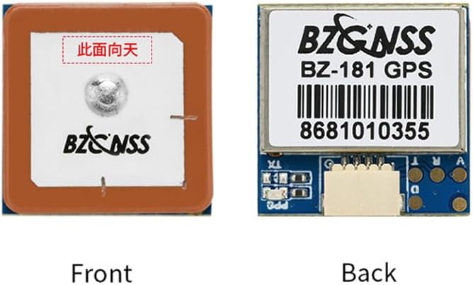
Image 4.1: Overview of BZGNSS BZ-121, BZ-181, and BZ-251 GPS modules.
4.1 BZ-121 Specifications
| Parameter | Specification |
|---|---|
| Chip | M10050 (Ten Generation Chip) |
| Pattern | GPS, GLONASS, BDS, GALILEO, SBAS, QZSS (Default: GPS+GLONASS+BDS) |
| FLASH | Supported |
| Frequency | GPS L1, GLONASS L1, BDS L1, GALILEO L1, SBAS L1, QZSS L1 |
| Power | 5V |
| Size | 12x16x4.5mm |
| Interface | PCB Pad |
| Weight | 2.2g |
| Antenna | Ultrathin Ceramic Antenna |
| Receiving Channels | 72 search channels |
| Baud Rate | 115200dps |
| Output Protocol | NMEA / UBLOX (Dual protocol) |
| Output Frequency | 1Hz-10Hz (Default 10Hz) |
| Speed Accuracy | 0.05m/s |
| Horizontal Positioning Accuracy | 2D ACC 1.5m (open air) |
| Receiving Sensitivity | Trace-162dBm / Capture -160dBm |
| Dynamic Characteristics (Altitude) | 50000m |
| Dynamic Characteristics (Speed) | 500m/s |
| Dynamic Characteristics (Acceleration) | 4G |
| Operating Temperature | -40°C ~ +85°C |
| Storage Temperature | -40°C ~ +105°C |
| Indicator Light | PPS lamp - off when not positioned, red flashes after 3D positioning |
4.2 BZ-181 Specifications
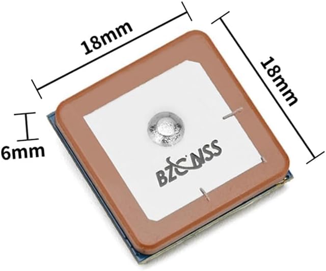

Image 4.2: BZ-181 GPS module dimensions (top and side views).

Image 4.3: BZ-181 GPS module weight (approximately 4.62g).
| Parameter | Specification |
|---|---|
| Chip | M10050 (Ten Generation Chip) |
| Pattern | GPS, GLONASS, BDS, GALILEO, SBAS, QZSS (Default: GPS+GLONASS+BDS) |
| FLASH | Supported |
| Frequency | GPS L1, GLONASS L1, BDS L1, GALILEO L1, SBAS L1, QZSS L1 |
| Power | 5V |
| Size | 18x18x4.8mm (Thinnest point), 18x18x6mm (Including terminal block) |
| Interface | SH1.0 4Pin |
| Weight | 6.9g |
| Antenna | Ultrathin Ceramic Antenna / Standard Ceramic Antenna |
| Receiving Channels | 72 search channels |
| Baud Rate | 115200dps |
| Output Protocol | NMEA / UBLOX (Dual protocol) |
| Output Frequency | 1Hz-10Hz (Default 10Hz) |
| Speed Accuracy | 0.05m/s |
| Horizontal Positioning Accuracy | 2D ACC 1.5m (open air) |
| Receiving Sensitivity | Trace-162dBm / Capture -160dBm |
| Dynamic Characteristics (Altitude) | 50000m |
| Dynamic Characteristics (Speed) | 500m/s |
| Dynamic Characteristics (Acceleration) | 4G |
| Operating Temperature | -40°C ~ +85°C |
| Storage Temperature | -40°C ~ +105°C |
| Indicator Light | PPS lamp - off when not positioned, red flashes after 3D positioning |
4.3 BZ-251 Specifications
| Parameter | Specification |
|---|---|
| Chip | M10050 (Ten Generation Chip) |
| Pattern | GPS, GLONASS, BDS, GALILEO, SBAS, QZSS (Default: GPS+GLONASS+BDS) |
| FLASH | Supported |
| Frequency | GPS L1, GLONASS L1, BDS L1, GALILEO L1, SBAS L1, QZSS L1 |
| Power | 5V |
| Size | 25x25x7.2mm (Thinnest point), 25x25x6mm (Including terminal block) |
| Interface | SH1.0 6Pin |
| Weight | 11.6g |
| Antenna | Ultrathin Ceramic Antenna / Standard Ceramic Antenna |
| Receiving Channels | 72 search channels |
| Compass | QMC5883 |
| Baud Rate | 115200dps |
| Output Protocol | NMEA / UBLOX (Dual protocol) |
| Output Frequency | 1Hz-10Hz (Default 10Hz) |
| Speed Accuracy | 0.05m/s |
| Horizontal Positioning Accuracy | 2D ACC 1.5m (open air) |
| Receiving Sensitivity | Trace-162dBm / Capture -160dBm |
| Dynamic Characteristics (Altitude) | 50000m |
| Dynamic Characteristics (Speed) | 500m/s |
| Dynamic Characteristics (Acceleration) | 4G |
| Operating Temperature | -40°C ~ +85°C |
| Storage Temperature | -40°C ~ +105°C |
| Indicator Light | Power on red light of TX light flashes (data output), PPS lamp - off when not positioned, red flashes after 3D positioning |
5. Setup and Installation
5.1 General Installation Guidelines
- Mounting: Securely mount the GPS module on your aircraft, ensuring it is as far as possible from sources of electromagnetic interference (e.g., motors, ESCs, video transmitters).
- Orientation: For optimal performance, ensure the ceramic antenna faces upwards towards the sky with an unobstructed view. Refer to the module orientation section below.
- Power Supply: Connect the module to a stable 5V power source. Incorrect voltage can damage the module.
- Data Connection: Connect the TX and RX pins to the appropriate UART ports on your flight controller.
5.2 BZ-181 Wiring Diagram
The BZ-181 module typically uses a SH1.0 4-Pin connector. The standard wiring configuration is as follows:
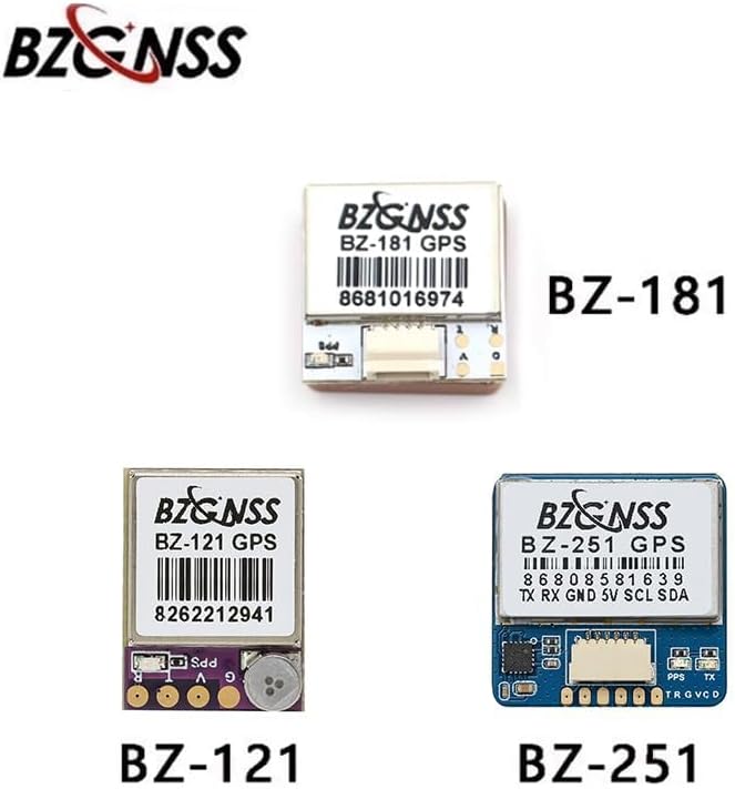
Image 5.1: BZ-181 GPS module wiring diagram. Connections include 5V (red), TX (yellow), GND (black), and RX (grey). An additional green wire is labeled as '备用GND' (Spare GND).
- Red Wire: 5V (Power Input)
- Yellow Wire: TX (Transmit Data, connect to Flight Controller RX)
- Black Wire: GND (Ground)
- Grey Wire: RX (Receive Data, connect to Flight Controller TX)
- Green Wire: Spare GND (Optional Ground)
5.3 Module Orientation
Correct orientation is crucial for optimal GPS signal reception. The ceramic antenna side of the module should always face upwards towards the sky.

Image 5.2: Front (antenna side) and back (PCB side) views of the BZ-181 module. The front side, marked with Chinese characters meaning 'This side up', should face the sky.
6. Operating Instructions
6.1 Power On and Initial Positioning
- Connect the GPS module to your flight controller and power on the system.
- Place the aircraft in an open outdoor area with a clear view of the sky.
- Observe the PPS indicator light on the module:
- If the light is off, the module has not yet achieved a position fix.
- Once a 3D position fix is achieved, the red PPS lamp will begin to flash, indicating successful satellite acquisition and data output.
- For BZ-251, the red TX light will flash when data is being outputted.
6.2 Output Protocol Configuration
The BZGNSS modules support both NMEA and UBLOX protocols. The default output frequency is 10Hz. Configuration of the desired protocol and other settings (e.g., update rate) is typically done via your flight controller's software (e.g., Betaflight, ArduPilot) or a dedicated UBLOX configuration tool if direct access to the module is required.
7. Maintenance
- Cleaning: Keep the module clean and free from dust and debris. Use a soft, dry cloth for cleaning. Avoid using liquids or solvents.
- Storage: Store the module in a dry, cool environment, away from direct sunlight and extreme temperatures.
- Handling: Handle the module by its edges to avoid touching the sensitive electronic components or the ceramic antenna.
- Antenna Protection: The ceramic antenna has an oil spraying process to prevent scratching and oxidation, but care should still be taken to avoid physical damage.
8. Troubleshooting
- No Position Fix (PPS light off):
- Ensure the module is in an open outdoor area with a clear view of the sky.
- Verify the module's orientation (antenna facing up).
- Check power connections (5V).
- Ensure no significant electromagnetic interference is present near the module.
- No Data Output (TX light not flashing for BZ-251, or no data on flight controller):
- Verify wiring connections (TX to FC RX, RX to FC TX, GND, 5V).
- Check flight controller UART settings (baud rate, protocol). The default baud rate is 115200dps.
- Ensure the flight controller firmware is configured to recognize the GPS module.
- Inaccurate Positioning:
- Relocate the aircraft to an area with better sky visibility.
- Check for potential sources of interference.
- Allow more time for the module to acquire satellites, especially during initial power-on or after long periods of inactivity.
9. Warranty and Support
For warranty information and technical support, please refer to the official SPARKHOBBY website or contact your retailer. Keep your purchase receipt as proof of purchase for any warranty claims. Detailed support resources, including firmware updates and advanced configuration guides, may be available online.