Introduction
This manual provides detailed instructions for the installation, operation, and maintenance of the FRPKPNOX DTS238-7 ZN/S 3 Phase Din Rail Energy Meter. Please read this manual thoroughly before installation and use to ensure proper function and safety.
Product Overview
The DTS238-7 ZN/S is a three-phase energy meter designed for DIN rail mounting. It accurately measures active energy (kWh) and features RS485 MODBUS-RTU communication for remote monitoring. It is suitable for 3x220/380V and 3x230/400V systems at 50Hz or 60Hz.

This image displays the front panel of the DTS238-7 ZN/S energy meter, showing the LCD display for energy readings (kWh), LED indicators for L1, L2, L3 phases, and pulse output, along with 'SET', 'Δ', and '∇' buttons for navigation and configuration. The model number DTS238-7 ZN/S and voltage/current ratings are also visible.
Specifications
The following table details the technical specifications of the DTS238-7 ZN/S energy meter:
| Parameter | Value |
|---|---|
| Meter Type | DTS238-7 ZN/S |
| Rated Frequency | 50 Hz and 60 Hz |
| Rated Current | 10(100)A |
| Rated Voltage | 3x220/380V, 3x230/400V |
| Normal Voltage Range | 90%Un - 110%Un |
| Limits Voltage Range | 70%Un - 120%Un |
| Accuracy Class | 1 |
| Pulse Constant | 400Imp/kWh |
| RS485 Port | MODBUS-RTU protocol, 1200-9600bps, None parity, default 9600bps |
| Package Dimensions | 1.18 x 0.79 x 0.39 inches |
| Item Weight | 1.76 ounces |
Installation and Wiring
The DTS238-7 ZN/S energy meter is designed for DIN rail mounting. Ensure all power is disconnected before proceeding with installation.
DIN Rail Mounting

This image shows the side profile of the DTS238-7 ZN/S energy meter, illustrating its compatibility with standard DIN rail mounting systems. The meter securely clips onto the rail, facilitating easy installation in electrical panels.
Wiring Diagram
Refer to the following diagram for correct wiring connections. Incorrect wiring can lead to malfunction or damage.
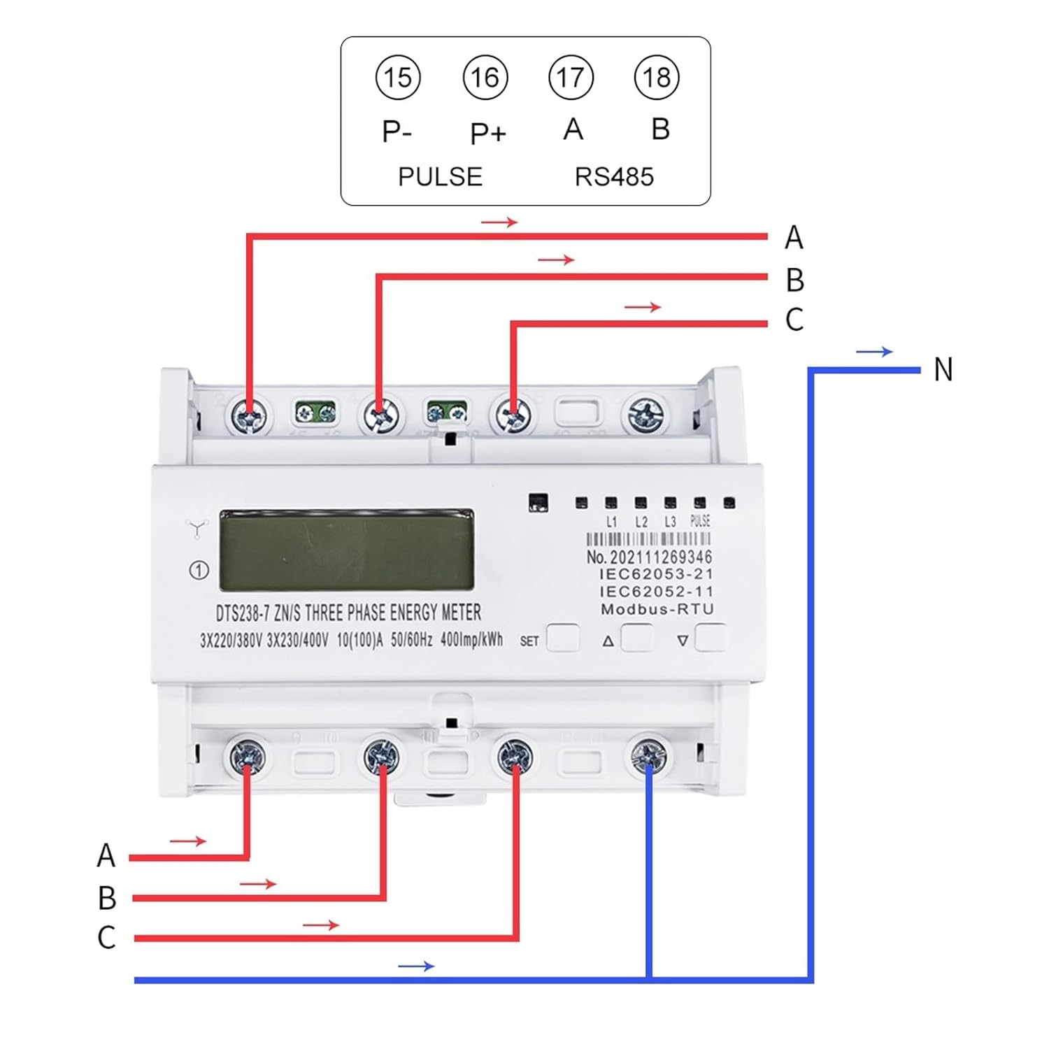
This diagram illustrates the wiring connections for the DTS238-7 ZN/S energy meter. It shows the input connections for phases A, B, C, and Neutral (N), as well as the output connections. Additionally, it details the connections for the Pulse output (P-, P+) and RS485 communication (A, B) terminals, labeled 15, 16, 17, 18 respectively.
- Connect the three-phase live wires (L1, L2, L3) to the corresponding input terminals (A, B, C).
- Connect the neutral wire (N) to the designated neutral input terminal.
- Connect the load wires from the output terminals.
- For pulse output, connect P- and P+ terminals (15, 16).
- For RS485 communication, connect A and B terminals (17, 18) to your MODBUS-RTU master device.
Operating Instructions
Display and Indicators
- LCD Display: Shows the total active energy consumption in kWh.
- L1, L2, L3 LEDs: Indicate the presence of voltage for each phase.
- PULSE LED: Flashes to indicate energy consumption (e.g., 400 pulses per kWh).
Button Functions
The meter features three buttons: 'SET', 'Δ' (Up), and '∇' (Down).
- SET Button: Used to enter and confirm settings menus.
- Δ (Up) Button: Used to navigate up through menu options or increase values.
- ∇ (Down) Button: Used to navigate down through menu options or decrease values.
RS485 Communication
The meter supports MODBUS-RTU protocol via its RS485 port. Default communication parameters are 9600bps, no parity. Refer to the MODBUS communication protocol documentation for detailed register addresses and commands.
Maintenance
- Keep the meter clean and free from dust. Use a dry, soft cloth for cleaning.
- Do not expose the meter to direct sunlight, extreme temperatures, or high humidity.
- Regularly check wiring connections for tightness and signs of wear.
- No user-serviceable parts inside. Do not attempt to open or repair the meter.
Troubleshooting
- No Display: Check power supply connections (L1, L2, L3, N). Ensure voltage is within the specified range.
- Incorrect Readings: Verify wiring according to the diagram. Ensure current transformers (if used, though this model seems direct connect up to 100A) are correctly installed and phased.
- RS485 Communication Failure: Check RS485 wiring (A, B). Verify communication parameters (baud rate, parity) match the master device. Ensure the MODBUS address is correctly set.
- LEDs Not Lit: Check phase voltage presence.
Warranty and Support
For warranty information and technical support, please contact your retailer or the manufacturer, FRPKPNOX. Keep your purchase receipt as proof of purchase.