1. Introduction
Thank you for choosing the BGFIVKAD XL830L Digital Multimeter. This device is designed for safe and accurate measurement of voltage, current, resistance, and for testing diodes, transistors, and continuity. Please read this manual thoroughly before use to ensure proper operation and safety.
Package Contents:
- 1 x XL830L Digital Multimeter
- 2 x Test Leads (Red and Black)
- 1 x User Manual
2. Safety Information
General Safety Warnings:
- Always ensure the multimeter is set to the correct function and range before making measurements.
- Do not exceed the maximum input values for each range.
- Exercise extreme caution when working with voltages above 30V AC RMS, 42V peak, or 60V DC. These voltages pose a shock hazard.
- Before measuring current, ensure the circuit is de-energized and the multimeter is connected in series.
- Before measuring resistance, diodes, or continuity, ensure the circuit is de-energized and all capacitors are discharged.
- Replace the battery immediately when the low battery indicator appears to ensure accurate readings.
- Do not operate the meter if it appears damaged or if the test leads are damaged.
- This meter is rated for CAT II 600V. Do not use it for measurements in CAT III or CAT IV environments.
3. Product Overview
The BGFIVKAD XL830L Digital Multimeter features a clear LCD display, a rotary function switch, and multiple input jacks for versatile measurements.

Image: Labeled diagram of the XL830L Digital Multimeter, indicating the LCD display, backlight button, OFF key, data retention button, DC voltage file, resistance file, diode file, transistor DC current socket, and input jacks.
Key Components:
- LCD Display: Shows measurement readings, units, and function indicators.
- Backlight Button: Activates the display backlight for improved visibility in low-light conditions.
- HOLD Button: Freezes the current reading on the display.
- Rotary Function Switch: Selects the desired measurement function and range.
- "VΩmA" Jack: Positive input terminal for voltage, resistance, and small current measurements.
- "COM" Jack: Common (negative) input terminal for all measurements.
- "10ADC" Jack: Positive input terminal for high DC current measurements (up to 10A).
- Transistor (hFE) Socket: For testing NPN and PNP transistors.
4. Setup
Battery Installation:
- The XL830L multimeter requires one 9V (6F22) battery.
- Locate the battery compartment cover on the back of the meter.
- Remove the screw(s) securing the cover and open it.
- Connect the 9V battery to the battery clip, observing correct polarity.
- Place the battery into the compartment and replace the cover, securing it with the screw(s).
Connecting Test Leads:
- Insert the black test lead into the "COM" (Common) jack.
- For most measurements (voltage, resistance, diode, continuity, and small current), insert the red test lead into the "VΩmA" jack.
- For high DC current measurements (up to 10A), insert the red test lead into the "10ADC" jack.
5. Operating Instructions
General Operation Notes:
- Always start with the highest range when measuring an unknown value to prevent overloading the meter.
- If the display shows "OL" (Overload), the measured value exceeds the selected range. Switch to a higher range.
- Ensure good contact between the test probes and the circuit points.
5.1. Measuring DC Voltage (V=)
- Set the rotary switch to the desired "V=" (DC Voltage) range (e.g., 20V, 200V, 600V).
- Connect the red test lead to the positive side of the circuit and the black test lead to the negative side.
- Read the voltage value on the LCD display.

Image: The XL830L Digital Multimeter displaying a DC voltage measurement of a 9V battery. The red probe is connected to the positive terminal and the black probe to the negative terminal.
5.2. Measuring AC Voltage (V~)
- Set the rotary switch to the desired "V~" (AC Voltage) range (e.g., 200V, 600V).
- Connect the test leads across the AC voltage source.
- Read the voltage value on the LCD display.
5.3. Measuring DC Current (A=)
- Important: De-energize the circuit before connecting the meter.
- Set the rotary switch to the desired "A=" (DC Current) range (e.g., 200µA, 2mA, 20mA, 200mA, 10A).
- For currents up to 200mA, connect the red test lead to the "VΩmA" jack. For currents up to 10A, connect the red test lead to the "10ADC" jack.
- Connect the meter in series with the circuit where current is to be measured.
- Re-energize the circuit and read the current value.
5.4. Measuring Resistance (Ω)
- Important: Ensure the circuit is de-energized and all capacitors are discharged before measuring resistance.
- Set the rotary switch to the desired "Ω" (Resistance) range (e.g., 200Ω, 2kΩ, 20kΩ, 200kΩ, 2MΩ).
- Connect the test leads across the component to be measured.
- Read the resistance value on the LCD display.

Image: The XL830L Digital Multimeter measuring the resistance of a component. The test leads are connected to the resistor, and the display shows the resistance value.
5.5. Diode Test
- Set the rotary switch to the diode symbol (►|).
- Connect the red test lead to the anode of the diode and the black test lead to the cathode.
- The display will show the forward voltage drop (typically 0.5V to 0.8V for silicon diodes). Reversing the leads should show "OL" for a good diode.
5.6. Transistor (hFE) Test
- Set the rotary switch to the "hFE" position.
- Identify if the transistor is NPN or PNP and its Emitter (E), Base (B), Collector (C) leads.
- Insert the transistor leads into the corresponding holes in the hFE socket.
- The display will show the hFE (DC current gain) value.
5.7. Continuity Test
- Set the rotary switch to the continuity symbol (sound wave).
- Connect the test leads across the circuit or component to be tested.
- If there is continuity (low resistance), the meter will emit an audible beep. The display will show the resistance value.
5.8. Data Hold Function
- Press the "HOLD" button to freeze the current reading on the display.
- Press "HOLD" again to release the reading.
5.9. Backlight Function
- Press the "BACK LIGHT" button to turn on the display backlight.
- Press "BACK LIGHT" again to turn it off.
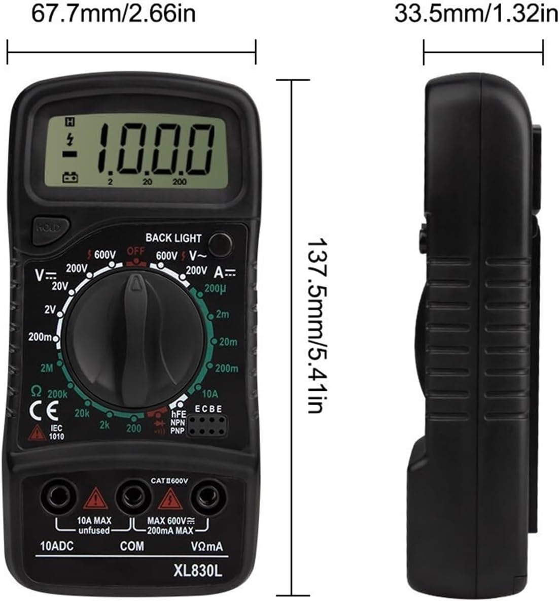
Image: The XL830L Digital Multimeter with its blue backlight activated, showing a reading on the LCD.
5.10. Low Battery Indication
- A battery symbol will appear on the LCD display when the battery voltage is low.
- Replace the 9V battery promptly to ensure accurate measurements.
6. Maintenance
Cleaning:
- Wipe the meter casing with a damp cloth and mild detergent. Do not use abrasives or solvents.
- Keep the input jacks free from dust and debris.
Battery Replacement:
- Refer to the "Battery Installation" section under "Setup" for detailed instructions.
- Always use a fresh 9V (6F22) battery.
Fuse Replacement (for 200mA range):
- The 10A current range is unfused. The 200mA range may have an internal fuse.
- If the meter fails to measure current in the mA range, the fuse may be blown.
- To replace the fuse, open the back cover (similar to battery replacement).
- Replace with a fuse of the same type and rating (e.g., F200mA/250V fast-blow type).
- Caution: Using an incorrect fuse can damage the meter or pose a safety hazard.
7. Troubleshooting
No Display or Faint Display:
- Check battery installation and polarity.
- Replace the 9V battery if it is low or depleted.
"OL" (Overload) Indication:
- The measured value exceeds the selected range. Switch to a higher range.
- Ensure the test leads are correctly connected for the measurement type.
Incorrect Readings:
- Ensure the function switch is set to the correct measurement type and range.
- Check for good contact between test probes and the circuit.
- Verify battery voltage; a low battery can affect accuracy.
- Ensure the circuit is de-energized for resistance, diode, and continuity tests.
No Current Measurement (mA range):
- Check if the internal fuse for the mA range is blown and replace if necessary (refer to Maintenance).
- Ensure the meter is connected in series with the circuit.
8. Specifications
General:
- Model: XL830L
- Display: LCD, 3 ½ digits (1999 counts)
- Power: 9V battery (6F22)
- Operating Temperature: 0°C to 40°C (32°F to 104°F)
- Storage Temperature: -10°C to 50°C (14°F to 122°F)
- Dimensions: 137.5 x 67.7 x 33.5 mm (5.41 x 2.66 x 1.32 inches)
- Weight: Approximately 50g (excluding battery)
- Safety Rating: CAT II 600V

Image: Dimensions of the XL830L Digital Multimeter, showing its length (137.5mm), width (67.7mm), and thickness (33.5mm).
Measurement Ranges:
- DC Voltage (V=): 200mV, 2V, 20V, 200V, 600V
- AC Voltage (V~): 200V, 600V
- DC Current (A=): 200µA, 2mA, 20mA, 200mA, 10A
- Resistance (Ω): 200Ω, 2kΩ, 20kΩ, 200kΩ, 2MΩ
- Diode Test: Yes
- Transistor (hFE) Test: Yes
- Continuity Test: Yes (with buzzer)
- Backlight: Yes
- Data Hold: Yes
- Low Battery Indication: Yes
9. Warranty and Support
For warranty information or technical support, please contact the seller or manufacturer directly through your purchase platform. Keep your proof of purchase for any warranty claims.