1. Introduction
The Copeland IC208CX-11000 is an advanced controller designed for precise management of heat pump systems and water chillers. This unit features 8 relay outputs, enabling control of up to 4 compressors, making it suitable for a wide range of industrial and commercial HVAC applications. Its robust design and comprehensive input/output capabilities ensure reliable performance and efficient system operation.
2. Safety Information
Please read all instructions carefully before installation and operation. Failure to follow these instructions may result in equipment damage, personal injury, or death. This device should only be installed and serviced by qualified personnel.
- Disconnect all power to the system before installing or servicing the controller.
- Ensure proper grounding to prevent electrical shock.
- Verify all wiring connections are secure and comply with local electrical codes.
- Do not expose the controller to excessive moisture or extreme temperatures outside its specified operating range.
- Use only specified power supply voltages (12Vac or 24 Vac/dc).
3. Product Overview
The IC208CX-11000 controller is housed in a durable PC + ABS casing with a PC frontal panel, designed for panel mounting. It features an IP65 frontal protection rating, ensuring resistance against dust and water ingress.
3.1 Front View

Figure 1: Front view of the IC208CX-11000 controller, showing the display, control buttons (SET, up/down arrows, Menu), and the Copeland logo.
3.2 Rear View and Wiring
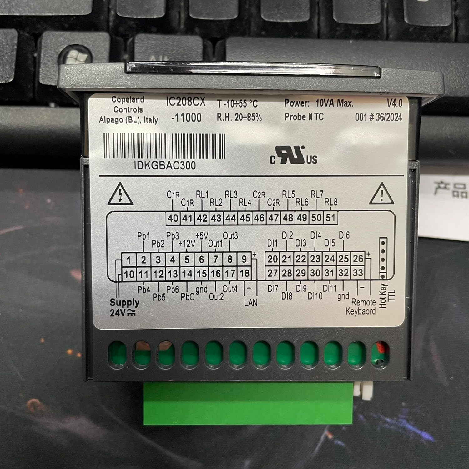
Figure 2: Rear view of the IC208CX-11000 controller, displaying the terminal block for electrical connections and detailed wiring labels. Note the model information "IC208CX -11000" and the Alapago (BL), Italy origin. A relevant link for further information is IDKGBAC300.
3.3 Side View
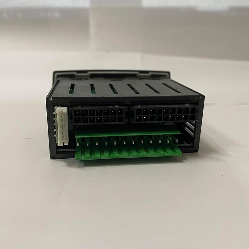
Figure 3: Side view of the IC208CX-11000 controller, illustrating the various connector ports for external modules or accessories.
4. Installation and Setup
4.1 Mounting
The IC208CX-11000 is designed for panel mounting. Create a panel cut-out with dimensions of 29x71mm. Insert the controller into the opening and secure it using the provided fasteners. Ensure the frontal panel is flush with the mounting surface for optimal IP65 protection.
4.2 Electrical Connections
Refer to Figure 2 for the detailed wiring diagram on the rear of the unit. All connections should be made by a qualified electrician.
- Power Supply: Connect 12Vac (-10% to +15%) or 24 Vac/dc (+10%) 50/60 Hz to the designated power terminals.
- Analog Inputs: The controller features 4 configurable analog inputs (NTC/PTC/digital input) and 2 additional configurable inputs (NTC/PTC/4-20mA/0-5Volt/digital input). Connect temperature probes (NTC/PTC) or other analog sensors as required by your system.
- Digital Inputs: There are 11 digital inputs available for free voltage signals. These can be used for various control signals such as pressure switches, flow switches, or defrost initiation.
- Relay Outputs: The IC208CX model provides 8 SPDT relays (5(2)A, 250Vac) for controlling compressors, fans, defrost heaters, and other system components. Ensure the maximum current on the common line does not exceed 10A.
- Data Storing: The controller utilizes non-volatile memory (EEPROM) for data storage, ensuring settings are retained even during power loss.
5. Operating Instructions
Once installed and powered, the controller's display will show the current operating status. Use the front panel buttons to navigate menus and adjust settings.
- SET Button: Used to enter parameter setting mode or confirm a selection.
- Up/Down Arrows: Used to navigate through menu options or adjust parameter values.
- MENU Button: Used to access the main menu or exit a sub-menu.
Detailed programming and parameter configuration instructions are typically found in the full technical manual, which can be obtained from the manufacturer's website or support channels. This manual focuses on general operation.
6. Maintenance
The IC208CX-11000 controller is designed for minimal maintenance. However, periodic checks are recommended to ensure optimal performance and longevity.
- Cleaning: Gently wipe the frontal panel with a soft, damp cloth. Do not use abrasive cleaners or solvents.
- Connection Check: Periodically inspect all wiring connections for tightness and signs of corrosion.
- Environmental Conditions: Ensure the operating environment remains within the specified temperature and humidity ranges to prevent damage.
7. Troubleshooting
This section provides basic troubleshooting steps for common issues. For complex problems, contact qualified service personnel.
| Problem | Possible Cause | Solution |
|---|---|---|
| Controller not powering on | No power supply; incorrect voltage; faulty wiring. | Check power connections and voltage. Ensure power supply is active. Verify wiring according to diagram. |
| Incorrect temperature reading | Faulty sensor; incorrect sensor type selected; poor sensor connection. | Check sensor wiring. Verify sensor type setting in controller parameters. Replace sensor if necessary. |
| Relay not activating | Incorrect parameter setting; faulty relay; wiring issue. | Check controller output parameters. Verify load wiring. Consult a technician if relay is suspected faulty. |
8. Specifications
| Parameter | Value |
|---|---|
| Material | Housing PC + ABS, Frontal Panel PC |
| Case Dimensions | 32x74 mm; depth 60mm |
| Mounting | Panel mounting in a 29x71mm cut-out |
| Frontal Protection | IP65 |
| Power Supply | 12Vac -10%-+15% or 24 Vac/dc +10% 50/60 Hz |
| Power Consumption | 10VA max. |
| Analog Inputs | 4 configurable (NTC/PTC/dig.input), 2 configurable (NTC/PTC/4-20mA/0-5Volt/dig. input) |
| Digital Inputs | 11 (free voltage) |
| Relay Outputs (IC208CX) | 8 relays SPDT 5(2)A, 250Vac |
| Max. Current on Common Line | 10A |
| Data Storing | Non-volatile memory (EEPROM) |
| Operating Temperature | -10 to 55 °C (14 to 131 °F) |
| Storage Temperature | -30 to 85 °C (-22 to 185 °F) |
| Relative Humidity | 20-85% (non-condensing) |
| Measuring Range (NTC/PTC) | -50 to 110 °C (-58 to 230 °F) |
| Measuring Range (NTC/PTC extended) | -50.0 to 150 °C (-58 to 302 °F) |
| Measuring Range (Pressure) | 0 to 50 bar (0 to 725 psi) |
| Resolution | 0.1 °C or 1 °F (NTC/PTC probes), 4..20mA and 0..5V probes |
9. Warranty and Support
For warranty information, technical support, or service inquiries, please contact the manufacturer or your authorized distributor. Keep your purchase receipt as proof of purchase.
Manufacturer: Copeland
Model: IC208CX-11000


