1. Product Overview
The HIRINTOL Electronic Control Module (ECM), also known as an ECM Controller, is a critical component designed for precise management of engine and generator set functions. This aftermarket part serves as a direct replacement for original equipment, ensuring reliable performance and compatibility.
This ECM is specifically programmed and compatible with a wide range of Caterpillar engines and generator sets, including models from the C9, C13, C15, C18, C27, C32, C4.4, C7.1, C1.5, C3.3, and 3406C series. It is available in EMCP 4.1 and EMCP 4.2 versions, providing advanced electronic control for optimal engine operation.

Figure 1: Front view of the Electronic Control Module (ECM) showing the display and control interface.
2. Product Features and Specifications
Key Features:
- Direct Replacement: Designed to directly replace original ECM units with part numbers 592-5150, 5925150, 30R-0042, and 30R0042.
- Broad Compatibility: Compatible with Caterpillar C9, C13, C15, C18, C27, C32, C4.4, C7.1, C1.5, C3.3, and 3406C Engine Generator Sets.
- Enhanced Durability: Manufactured with improved circuitry for enhanced functionality and increased longevity.
- Pre-Programmed: Modules are programmed to your engine’s exact specifications, ensuring immediate installation and functionality upon receipt.
- Quality Manufacturing: Undergoes a precise inspection process to ensure reliability and performance.
Specifications:
| Attribute | Detail |
|---|---|
| Part Name | ECM Controller, Electronic Control Module |
| Fuel Type | Diesel |
| Material | Metal |
| Item Condition | Aftermarket Part |
| Way of Use | Direct Replacement |
| Version | EMCP 4.1, EMCP 4.2 |
| Reference Numbers | 592-5150, 5925150, 30R-0042, 30R0042 |

Figure 2: Rear view of the ECM, highlighting the product label and connection points.
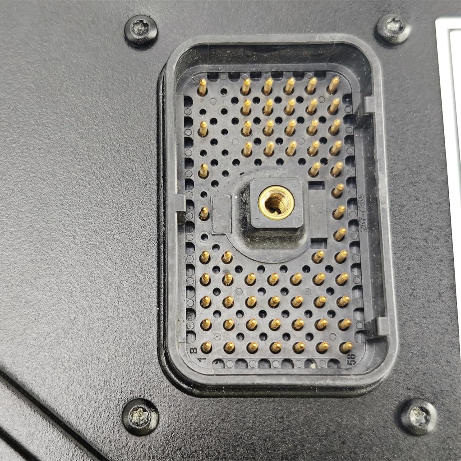
Figure 3: Detailed view of the ECM's electrical connector pins.
3. Setup and Installation
Installation of the Electronic Control Module requires specialized knowledge and tools. It is strongly recommended that installation and removal be performed by an experienced and qualified technician.
Important Installation Notes:
- Professional Installation: Due to the complexity of engine control systems, an experienced technician is always recommended for the installation or removal of the Engine Control Module.
- Module Programming: Programming of the module is required for it to function correctly with your specific engine. Each engine has unique requirements that must be configured within the ECM.
- Information Required for Programming: To ensure proper programming and compatibility, please provide the following information after purchase:
- Original Module Part Number and a clear picture of the original module.
- Vehicle Model and Serial Number (if applicable).
- Engine Model and Serial Number.
- Secure Connections: Ensure all electrical connections are clean, secure, and properly seated to prevent intermittent issues or damage.

Figure 4: Angled view of the ECM, illustrating its compact design.
4. Operating Principles
The Electronic Control Module (ECM) is the central processing unit for your engine's electronic management system. Once properly installed and programmed, it continuously monitors various engine sensors and actuators to optimize performance, fuel efficiency, and emissions.
The EMCP 4.1/4.2 interface, visible on the front of the module, allows for interaction with the engine's control system. This interface typically provides real-time data, fault codes, and access to various operational parameters. Specific operational details and menu navigation will depend on the engine's overall control system and the programming of the ECM.
Key Functions:
- Engine Monitoring: Collects data from sensors (e.g., temperature, pressure, speed).
- Fuel Injection Control: Manages fuel delivery for optimal combustion.
- Ignition Timing: Adjusts ignition timing for efficiency and power.
- Diagnostic Capabilities: Stores and displays fault codes for troubleshooting.
- Protection Features: Implements safeguards against engine damage from abnormal conditions.

Figure 5: Side profile of the ECM.
5. Maintenance
The HIRINTOL Electronic Control Module is designed for long-lasting performance and typically requires minimal direct maintenance. However, proper care of the surrounding environment and connections is crucial for its longevity and reliable operation.
General Maintenance Guidelines:
- Keep Clean and Dry: Ensure the ECM and its connections are kept free from dirt, moisture, and corrosive substances. Regularly inspect the housing for any signs of damage or ingress.
- Inspect Connections: Periodically check all electrical connections to the ECM for tightness and corrosion. Loose or corroded connections can lead to intermittent issues or module damage.
- Avoid Physical Impact: Protect the module from physical shocks or impacts, which can damage internal components.
- Environmental Control: Ensure the operating environment adheres to the engine manufacturer's specifications regarding temperature and vibration.

Figure 6: Top-angled view of the ECM.
6. Troubleshooting
If you experience issues with your engine or generator set that you suspect are related to the ECM, it is important to approach troubleshooting systematically. Given the complexity of these systems, professional diagnostic assistance is highly recommended.
Common Troubleshooting Steps (for qualified personnel):
- Check for Diagnostic Codes: Utilize the EMCP interface or a compatible diagnostic tool to retrieve any active or logged fault codes. These codes provide crucial information about the nature of the problem.
- Inspect Wiring and Connections: Visually inspect all wiring harnesses connected to the ECM for signs of damage, fraying, or loose connections. Ensure connectors are fully seated.
- Verify Power Supply: Confirm that the ECM is receiving proper power and ground connections according to the engine's electrical schematics.
- Review Programming: If the ECM was recently installed or reprogrammed, verify that the correct software and parameters were loaded for your specific engine model and serial number. Incorrect programming is a common cause of operational issues.
- Consult Service Manuals: Refer to the specific service manual for your Caterpillar engine model for detailed diagnostic procedures related to the ECM and associated components.
- Professional Diagnosis: If basic checks do not resolve the issue, or if you are unsure about any step, contact a qualified engine technician or the product support team for professional diagnosis and repair.
7. Warranty and Support
Warranty Period:
This HIRINTOL Electronic Control Module comes with a 12-month warranty period from the date of purchase. During this period, if any problems arise due to manufacturing defects or material failures, repair or replacement services will be provided.
Customer Support:
For any questions regarding installation, operation, troubleshooting, or warranty claims, please contact the seller or HIRINTOL customer support. When contacting support, please have your purchase details, the product's part number, and the engine's model and serial number readily available to facilitate a quicker resolution.
We are committed to providing a good buying experience and reliable after-sales service.


