
1. Introduction
The GuliTech MAS830L is a compact and reliable digital multimeter designed for basic electrical measurements. It features a 2000-count display, continuity buzzer, data hold function, and low battery indication. This manual provides essential information for safe and effective use of your MAS830L multimeter.
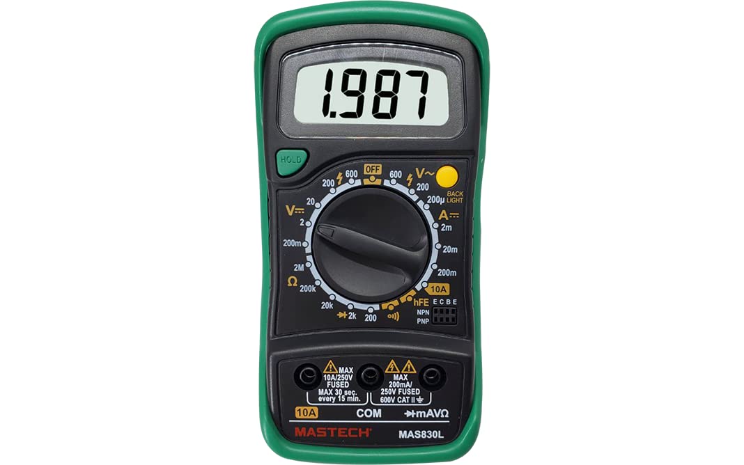
Image 1.1: The GuliTech MAS830L Digital Multimeter, showing its display, rotary switch, input jacks, and included test leads.
2. Safety Information
To ensure safe operation, always adhere to the following safety precautions:
- Do not exceed the maximum input limits for any range. The MAS830L is rated for CAT II 600V and CAT III 600V.
- Inspect test leads for damaged insulation or exposed metal before each use. Replace if damaged.
- Do not use the multimeter if it appears damaged or if the case is open.
- Exercise extreme caution when working with live circuits. High voltage can cause electric shock.
- Always disconnect power to the circuit and discharge high-voltage capacitors before measuring resistance, continuity, or diodes.
- Ensure the rotary switch is in the correct position for the desired measurement before connecting the test leads to the circuit.
- Replace the battery immediately when the low battery indicator appears to ensure accurate readings.
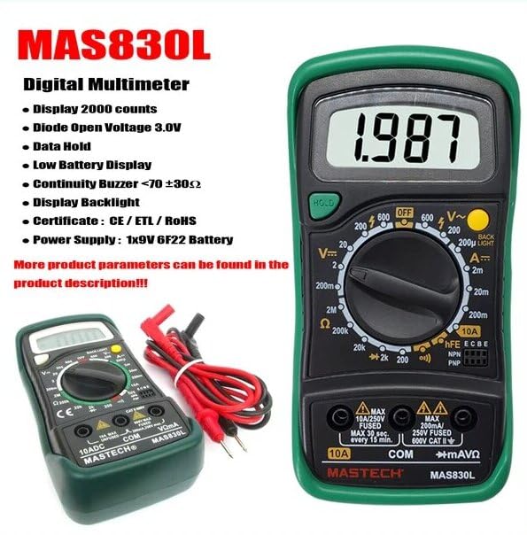
Image 2.1: Close-up view of the test probes, highlighting the importance of inspecting their condition before use.
3. Product Overview
Familiarize yourself with the components of your MAS830L Digital Multimeter:
- LCD Display: Shows measurement readings, units, and function indicators. Features a 2000-count display.
- Rotary Switch: Used to select the desired measurement function (Voltage, Current, Resistance, Diode, Continuity).
- HOLD Button: Freezes the current reading on the display. Press again to release.
- Backlight Button: Activates the display backlight for improved visibility in low-light conditions.
- Input Jacks:
- COM (Common): Connect the black test lead here.
- VΩmA: Connect the red test lead here for Voltage, Resistance, Diode, Continuity, and small Current measurements (mA).
- 10A: Connect the red test lead here for high Current measurements (up to 10A). This input is fused.

Image 3.1: The high-definition LCD screen of the MAS830L, providing clear and easy-to-read data.
4. Setup
4.1 Battery Installation
The MAS830L requires one 9V (6F22) battery for operation. To install or replace the battery:
- Ensure the multimeter is turned off and test leads are disconnected.
- Locate the battery compartment cover on the back of the unit.
- Unscrew the retaining screw(s) and carefully remove the cover.
- Connect the 9V battery to the battery clips, observing correct polarity.
- Place the battery into the compartment and replace the cover, securing it with the screw(s).
4.2 Connecting Test Leads
Always connect the black test lead to the COM jack. Connect the red test lead to the appropriate input jack based on the measurement you intend to perform (VΩmA or 10A).
5. Operating Instructions
5.1 General Operation
- Power On/Off: Rotate the switch from the OFF position to any desired function to turn on the multimeter. Rotate back to OFF to power off.
- Auto Power Off: The multimeter may feature an auto power-off function to conserve battery life. If present, it will automatically turn off after a period of inactivity.
- Data Hold: Press the 'HOLD' button to freeze the current reading on the display. Press again to resume live readings.
- Backlight: Press the 'Backlight' button to illuminate the display. Press again to turn off.
5.2 Measurement Functions
Follow these steps for various measurements:
- DC Voltage (V=):
- Set the rotary switch to the desired DC Voltage range (e.g., 20V, 200V, 600V).
- Connect the black test lead to COM and the red test lead to VΩmA.
- Connect the test probes across the component or circuit to be measured, observing polarity.
- AC Voltage (V~):
- Set the rotary switch to the desired AC Voltage range (e.g., 200V, 600V).
- Connect the black test lead to COM and the red test lead to VΩmA.
- Connect the test probes across the AC voltage source.
- DC Current (A=):
- Important: For current measurements, the multimeter must be connected in series with the circuit.
- Set the rotary switch to the desired DC Current range (e.g., 200mA, 10A).
- For measurements up to 200mA, connect the black test lead to COM and the red test lead to VΩmA.
- For measurements up to 10A, connect the black test lead to COM and the red test lead to 10A.
- Open the circuit where current is to be measured and connect the multimeter in series.
- Resistance (Ω):
- Ensure the circuit is de-energized and all capacitors are discharged.
- Set the rotary switch to the desired Resistance range (e.g., 200Ω, 2kΩ, 2MΩ).
- Connect the black test lead to COM and the red test lead to VΩmA.
- Connect the test probes across the component to be measured.
- Diode Test:
- Ensure the circuit is de-energized.
- Set the rotary switch to the Diode symbol.
- Connect the black test lead to COM and the red test lead to VΩmA.
- Connect the red probe to the anode and the black probe to the cathode of the diode. A forward voltage drop (e.g., 0.5V to 0.8V for silicon diodes) will be displayed. Reverse the probes; the display should show 'OL' (Open Loop).
- Continuity Test:
- Ensure the circuit is de-energized.
- Set the rotary switch to the Continuity symbol.
- Connect the black test lead to COM and the red test lead to VΩmA.
- Connect the test probes across the circuit or component. If the resistance is less than approximately 70 Ω ± 30 Ω, the buzzer will sound, indicating continuity.
6. Maintenance
6.1 Cleaning
Wipe the case with a damp cloth and mild detergent. Do not use abrasives or solvents. Keep the input terminals free from dirt and moisture.
6.2 Battery Replacement
Refer to Section 4.1 for battery replacement instructions. Always use a fresh 9V (6F22) battery.
6.3 Fuse Replacement
The 10A input jack is protected by a fuse. If the 10A current measurement function stops working, the fuse may need replacement. This typically requires opening the multimeter case. Refer to the specifications for the correct fuse type (e.g., 10A/250V FUSED).
6.4 Storage
If the multimeter is not used for an extended period, remove the battery to prevent leakage and damage.
7. Troubleshooting
If you encounter issues with your MAS830L, consider the following:
- No Display / Faint Display: Check the battery. Replace if low or depleted.
- Incorrect Readings: Ensure the rotary switch is set to the correct function and range. Check test lead connections. Verify the battery level.
- No Continuity Buzzer: Ensure the rotary switch is on the continuity setting. Check if the circuit resistance is within the buzzer's threshold (<70 Ω ± 30 Ω).
- 10A Current Measurement Not Working: The fuse for the 10A input may be blown. Refer to Section 6.3 for fuse replacement.
- 'OL' (Overload) Display: The measured value exceeds the selected range. Select a higher range or ensure the circuit is properly connected.
8. Specifications
Key technical specifications for the GuliTech MAS830L Digital Multimeter:
| Feature | Specification |
|---|---|
| Display | 2000 Counts |
| DC Voltage (V=) | Up to 600V |
| AC Voltage (V~) | Up to 600V |
| DC Current (A=) | Up to 10A |
| Resistance (Ω) | Up to 2MΩ |
| Diode Open Voltage | 3.0V |
| Continuity Buzzer | <70 Ω ± 30 Ω |
| Low Battery Display | Yes |
| Data Hold | Yes |
| Power Supply | 1 x 9V (6F22) Battery |
| Dimensions (L x W x H) | 16 x 9 x 5 cm |
| Weight | 500 grams |
| Safety Rating | CAT II 600V, CAT III 600V |
| Certifications | CE, RoHS |

Image 8.1: Overview of MAS830L features, main applications (domestic, electronics), and package contents (test leads, 9V battery, calibration certificate, quick start guide).

Image 8.2: Detailed comparison table showing specifications for various digital multimeters, including the MAS830L, highlighting its safety rating, display counts, and measurement ranges.
9. Warranty and Support
9.1 Warranty Information
The GuliTech MAS830L Digital Multimeter comes with a 1-year warranty from the date of purchase. This warranty covers manufacturing defects and ensures the product meets its specified performance under normal use. Please retain your proof of purchase for warranty claims.
9.2 Customer Support
For technical assistance, troubleshooting beyond this manual, or warranty inquiries, please contact your retailer or the GuliTech customer support team. Refer to the product packaging or the seller's information for contact details.