1. Introduction
This manual provides detailed instructions for the installation, operation, and maintenance of your BAIYITONGDA 1200W MPPT Hybrid Wind Solar Charge Controller. This controller is designed for 12V, 24V, or 48V systems, with this specific model configured for 12V. It efficiently manages power from both wind turbines and solar panels to charge batteries, ensuring optimal performance and system longevity. Please read this manual thoroughly before installation and use to ensure safe and correct operation.
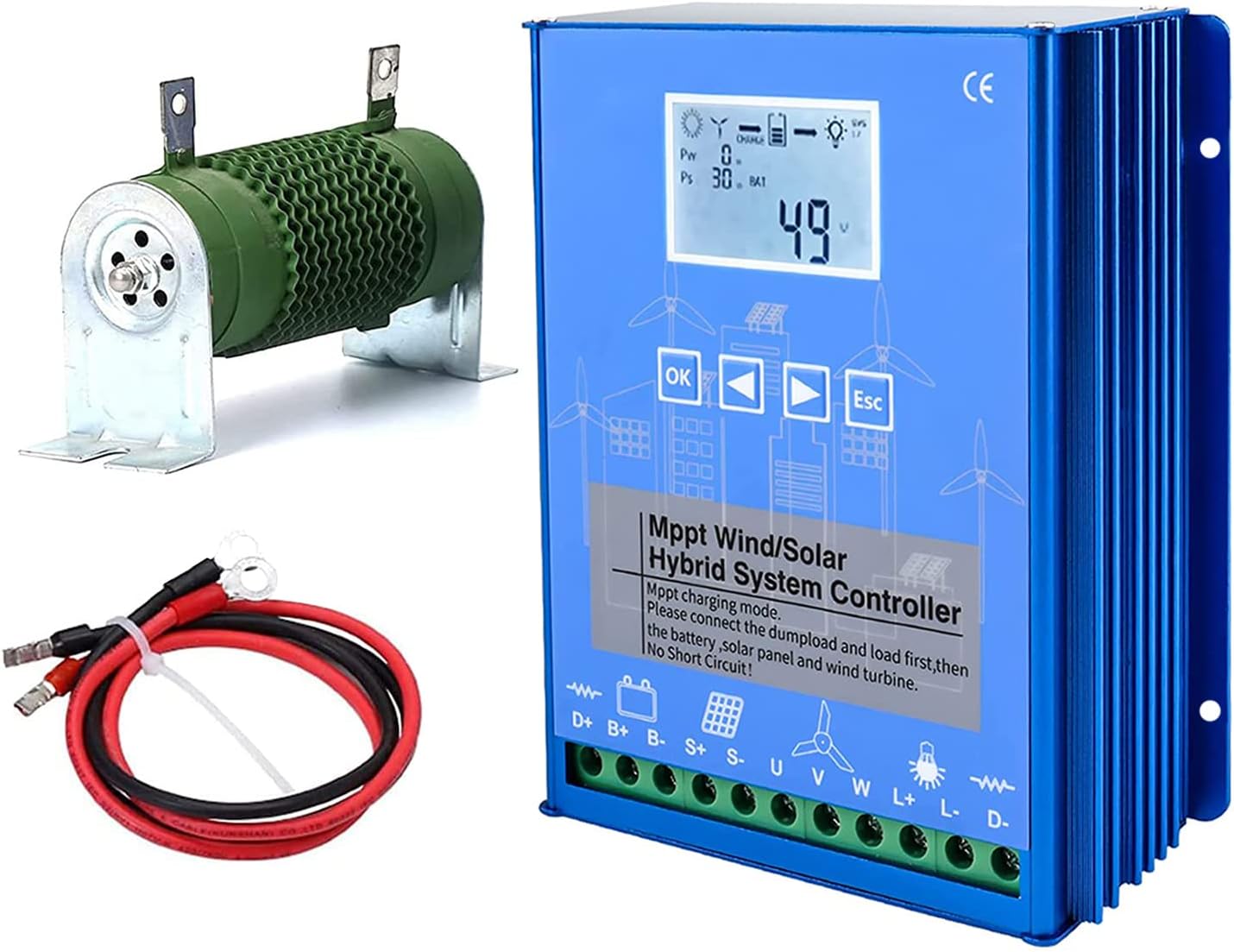
Figure 1: BAIYITONGDA 1200W MPPT Hybrid Wind Solar Charge Controller, including the main unit, external dump load resistor, and connection cables.
2. Product Features
The BAIYITONGDA Hybrid Wind Solar Charge Controller incorporates advanced technology to optimize energy harvesting and battery charging. Key features include:
- MPPT Wind Turbine Charging: Utilizes Maximum Power Point Tracking (MPPT) technology for the wind turbine input, ensuring continuous and efficient charging even at low wind speeds.
- PWM Solar Panel Charging: Employs Pulse Width Modulation (PWM) technology for solar panel charging via MOS tube in series, providing stable and controlled charging.
- Stepless PWM Fan Discharge: Features a stepless PWM fan discharge system with an external dump-load resistance for effective excess energy dissipation.
- Dual Power Supply: The controller can be powered by both the battery and solar energy, enhancing operational reliability.
- Intelligent System Control: Automatically sets parameters based on selected battery type, with options for user customization. Ensures stable charge voltage.
- LCD Display: A large LCD screen provides easy monitoring and control of system parameters, including wind power, solar power, battery voltage, and load status.
- Multiple DC Load Modes: Two DC load outputs with four selectable modes (e.g., light control, time control, morning light) for diverse applications.
- Comprehensive Protection Functions: Includes reversed charging protection for solar, overcharge/undervoltage protection, overload protection, battery reverse connection protection, open circuit protection, and lightning protection.
- Durable Construction: The internal circuit board is coated with three-proof paint to protect against dust, moisture, and static electricity.

Figure 2: Internal view of the controller, highlighting the high-performance chip and robust circuit board design, which includes protection against short-circuit, reverse polarity, over-charge, and over-discharge.

Figure 3: Visual representation of the controller's protection features, including Reverse Charge Protection, Reverse Polarity Protection, Overload Protection, Overcurrent/Overvoltage Protection, Open Circuit Protection, and Automatic Brake Protection.
3. Specifications
| Parameter | Value |
|---|---|
| Product Type | Wind and Solar Hybrid Controller |
| Material | Aluminum Alloy |
| Rated System Voltage | 12V (also compatible with 24V, 48V models) |
| Controller Dimensions | 16.7 x 14.5 x 6.18 cm (approx. 6.57 x 5.71 x 2.43 inches) |
| Maximum Wind Turbine Input Voltage | ≤80V |
| No-load Current (DC) | ≤0.05A |
| Cooling Method | Aluminum profile heat dissipation and self-cooling |
| Working Temperature / Relative Humidity | -25℃ ~ +80℃ / 0 ~ 90% (non-condensing) |
| Controller Power Supply Mode | Battery or Solar Energy |
| Control Mode | Wind turbine MPPT boost charging, PWM unloading, PWM overcurrent limiting |
4. Safety Instructions
Please observe the following safety precautions during installation and operation to prevent injury or damage to the equipment:
- Qualified Personnel: Installation and maintenance should only be performed by qualified personnel with knowledge of electrical systems and safety procedures.
- Disconnect Power: Always disconnect all power sources (wind turbine, solar panels, battery) before installing or servicing the controller.
- Correct Polarity: Ensure all connections are made with correct polarity. Reverse polarity can severely damage the controller and connected components.
- No Short Circuits: Prevent short circuits between terminals. This is critical during wiring.
- Proper Grounding: Ensure the system is properly grounded according to local electrical codes.
- Ventilation: Install the controller in a well-ventilated area to allow for proper heat dissipation.
- Environmental Conditions: Avoid exposing the controller to direct sunlight, rain, excessive dust, or corrosive environments.
- Battery Safety: Batteries can produce explosive gases. Ensure adequate ventilation when working with batteries and avoid sparks or open flames. Wear appropriate personal protective equipment (PPE).
- Dump Load Connection: The external dump load resistor must be connected before connecting the wind turbine to prevent overvoltage.
5. Setup and Installation
Follow these steps carefully for proper installation of the hybrid charge controller. It is crucial to connect components in the specified order to prevent damage.
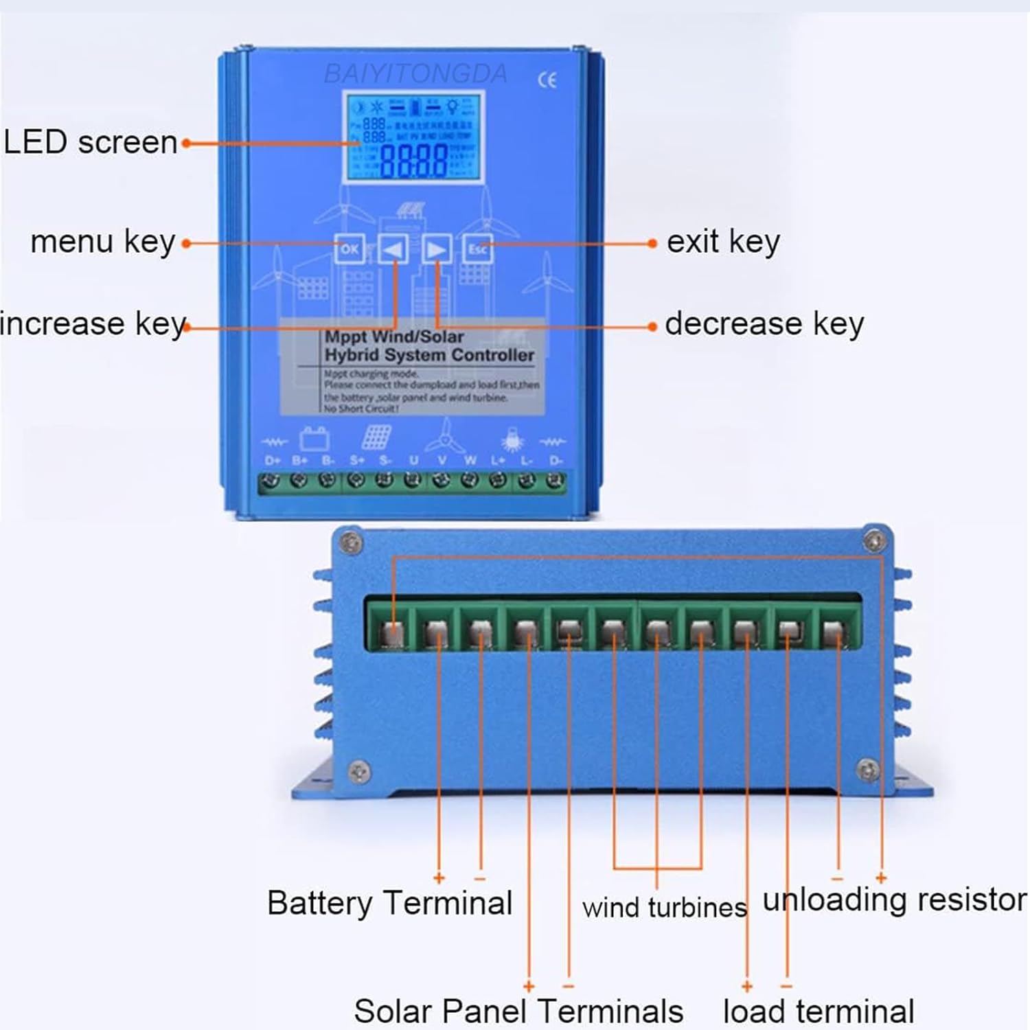
Figure 4: Front and bottom views of the controller, indicating the LED screen, menu keys (OK, increase, decrease, exit), and terminal connections for Battery, Solar Panel, Wind Turbines, Unloading Resistor, and Load.
5.1 Wiring Diagram and Connection Order
Refer to the wiring diagram below for correct connections. The connection order is critical:
- Connect the Unloading Resistor (Dump Load): Connect the external dump load resistor to the "Unloading Resistor" terminals on the controller. This must be connected first.
- Connect the DC Load: If applicable, connect your DC loads to the "Load Terminal" on the controller.
- Connect the Battery: Connect the battery to the "Battery Terminal" (D+ and D-) on the controller. Ensure correct polarity. The controller will power on once the battery is connected.
- Connect the Solar Panels: Connect the solar panel array to the "Solar Panel Terminals" (S+ and S-) on the controller. Ensure correct polarity.
- Connect the Wind Turbine: Connect the wind turbine to the "Wind Turbines" terminals (U, V, W) on the controller.
Important: Always ensure no short circuits occur during wiring. Disconnect in reverse order: Wind Turbine, Solar Panels, Battery, DC Load, Unloading Resistor.

Figure 5: Comprehensive wiring diagram illustrating the connection points for the Wind Turbine, Solar Panel, Battery, Inverter (for AC loads), DC Load, and the Unloading Device (dump load resistor) to the hybrid charge controller.
6. Operating Instructions
The controller features an intuitive LCD display and control buttons for monitoring and configuration.
6.1 LCD Display Overview

Figure 6: Detailed breakdown of the LCD screen, showing icons for Day/Night, Wind Turbine rotation, Charge status, Brake status, Battery pattern, System voltage (12V/24V/AUTO), Current wind turbine charging power (Pw), Current wind PV charging power (Ps), and the main display for browsing content parameters.
The LCD displays various system parameters and status indicators:
- Day/Night Icon (①): Indicates day or night. The night icon is displayed if no PV (solar) is connected.
- Wind Turbine Icon (②): Shows when the wind turbine is rotating.
- Charge Icon (③): Arrow flashes when PV and wind turbine are charging normally.
- Brake Icon (③): Indicates wind turbine brake is active (usually for 10 minutes).
- Battery Pattern (④): Shows battery charge level. Flashes during over-discharge protection and returns to normal when voltage recovers.
- Load Output Icon (⑤): Arrow flashes when the controller load output is active.
- System Voltage (⑥): Displays the locked system voltage (e.g., 12V, 24V) or "AUTO" if automatically identified.
- Wind Turbine Charging Power (⑦ Pw): Displays current wind turbine charging power.
- Solar PV Charging Power (⑦ Ps): Displays current solar PV charging power.
- Main Display (⑧): Shows current browsing content parameters (e.g., battery voltage, current, temperature).
6.2 Control Buttons
- OK Button: Used to enter menu, confirm selections, or cycle through display modes.
- Up Arrow Button: Used to increase values or navigate up in menus.
- Down Arrow Button: Used to decrease values or navigate down in menus.
- ESC Button: Used to exit menus or cancel selections.
6.3 Setting Parameters
The controller allows for customization of various parameters. Specific steps for navigating menus and adjusting settings will vary based on the firmware version. Generally:
- Press the OK button to enter the main menu or cycle through display screens.
- Use the Up and Down arrow buttons to navigate between parameters.
- Press OK again to select a parameter for editing.
- Use the Up and Down arrow buttons to adjust the value.
- Press OK to confirm the new value.
- Press ESC to exit the current menu or return to the previous screen.
Refer to the on-screen prompts and the detailed icon descriptions (Figure 6) to understand the current status and available settings. The controller automatically identifies the system voltage (12V, 24V, or 48V) upon initial battery connection, but this can often be manually locked or adjusted in settings.
7. Maintenance
Regular maintenance ensures the longevity and optimal performance of your hybrid charge controller.
- Visual Inspection: Periodically inspect the controller and all connections for any signs of damage, corrosion, or loose wiring.
- Cleanliness: Keep the controller clean and free from dust and debris. Use a dry, soft cloth for cleaning. Do not use liquids or abrasive cleaners.
- Ventilation: Ensure that the ventilation fins are not obstructed to allow for proper heat dissipation.
- Connection Tightness: Check all terminal connections periodically to ensure they are tight. Loose connections can cause overheating and poor performance.
- Battery Health: Monitor battery voltage and health regularly. A failing battery can impact the entire system.
- Environmental Check: Ensure the operating environment remains within the specified temperature and humidity ranges.
8. Troubleshooting
This section provides guidance for common issues. For problems not listed here, please contact customer support.
| Problem | Possible Cause | Solution |
|---|---|---|
| Controller not powering on | Battery not connected or low voltage; reverse polarity. | Check battery connections and voltage. Ensure correct polarity. Recharge battery if necessary. |
| No charging from solar panels | Solar panels not connected; low sunlight; reverse polarity; damaged panel/wiring. | Verify solar panel connections and polarity. Check for adequate sunlight. Inspect panels and wiring for damage. |
| No charging from wind turbine | Wind turbine not connected; insufficient wind speed; turbine brake active; damaged turbine/wiring. | Verify wind turbine connections. Check wind speed. Ensure turbine brake is not engaged. Inspect turbine and wiring. |
| Load not working | Load not connected; load output disabled in settings; overload protection active; low battery voltage. | Check load connections. Verify load output settings on the controller. Reduce load if overloaded. Check battery voltage. |
| Overheating | Poor ventilation; excessive load; high ambient temperature. | Ensure adequate airflow around the controller. Reduce load if possible. Relocate controller to a cooler area if ambient temperature is too high. |
9. Package Contents
The package for the BAIYITONGDA 1200W MPPT Hybrid Wind Solar Charge Controller typically includes:
- 1x Hybrid Wind Solar Charge Controller
- 1x External Dump Load Resistor
- 1x Connection Wire Set
- 1x User Manual (this document)
10. Warranty and Support
BAIYITONGDA products are manufactured to high-quality standards. For any questions or technical assistance, please contact our customer support. We aim to respond to inquiries within 24 hours.
Please retain your purchase receipt for warranty purposes.
Manufacturer: BAIYITONGDA