
1. Introduction
This manual provides detailed instructions for the Hilitand DC 5V-36V Timer Module. This versatile trigger cycle delay timer switch with an LED display is designed for various applications requiring precise timing control for DC loads. It features high performance, a long service life, and supports a wide voltage input range.
2. Product Overview and Components
The Hilitand DC Timer Module is equipped with an LED display for time indication, control buttons for setting parameters, and terminal blocks for power input, trigger signal, and load output.

Image 2.1: Front view of the Hilitand DC Timer Module, showing the LED display, control buttons (STOP, SET, UP, DOWN), input/output terminals, and trigger signal input. Key components are labeled for easy identification.
Key Components:
- LED Display: Shows current time settings and operating status.
- STOP Button: Used to set the clocking range.
- SET Button: Used to enter mode selection and confirm parameter settings.
- UP/+ Button: Adjusts parameter values upwards.
- DOWN/- Button: Adjusts parameter values downwards.
- Input Power Terminals: Connect DC 5V-36V power supply.
- Trigger Signal Input (SIGN): Accepts DC 3-24V trigger signal.
- Output Power Terminals (OUT+, OUT-): Connect to the load (DC 5V-36V, up to 15A/400W).
- MOS Connecting Indicator (LED1): Indicates MOS activity.
3. Setup and Wiring
Proper wiring is crucial for the safe and correct operation of the timer module. Ensure all connections are secure before applying power.
Wiring Diagram:
Image 3.1: Detailed wiring connections for the Hilitand DC Timer Module. Connect input power to the right-side terminals, the trigger signal to the 'SIGN' terminal, and the load to the 'OUT' terminals.
Connection Steps:
- Power Input: Connect your DC 5V-36V power supply to the input terminals on the right side of the module. Ensure correct polarity (+ to + and - to -).
- Trigger Signal: Connect your DC 3-24V trigger signal source to the 'SIGN' terminal. The 'GND T' terminal is for the trigger signal ground, which can be the same as the system ground.
- Load Output: Connect your DC load (e.g., motor, light, LED strip, micro-pump, solenoid valve) to the 'OUT+' and 'OUT-' terminals on the right side. The module supports loads up to 15A and 400W.
- Ground Connections: Ensure all ground connections (GND, GND T) are properly established.
Note: The module features reverse input protection. Dual-MOS in parallel active output ensures lower internal resistance and higher current capacity.
4. Operating Modes
The module supports several operating modes, each designed for specific timing applications. Understanding these modes is key to utilizing the module effectively.
- P1: Trigger Signal, Relay On 'OP' Time, Then Disconnect
- P1.1: Signal is triggered again, invalid (timing continues without interruption).
- P1.2: Signal is triggered again, the clocking is reset (timing restarts from zero).
- P1.3: Signal is triggered again, reset, relay off, and stop the clocking (relay turns off immediately and timing stops).
- P-2: Trigger Signal, Relay Off 'CL' Time, Relay On 'OP' Time, Then Disconnect
Upon receiving a trigger signal, the relay remains off for the 'CL' (off) time, then turns on for the 'OP' (on) time, and finally disconnects.
- P3.1: Trigger Signal, Relay On 'OP' Time, Relay Off 'CL' Time, Then Cycle
After a trigger signal, the relay turns on for 'OP' time, then off for 'CL' time, and this operation cycles for a set number of times ('LOP'). If a trigger signal is received again during the cycle, the relay turns off and stops clocking.
- P3.2: No Trigger Signal After Power On, Relay On 'OP' Time, Relay Off 'CL' Time, Then Cycle
Without an initial trigger signal after power-on, the relay turns on for 'OP' time, then off for 'CL' time, and this operation cycles for a set number of times ('LOP').
- P-4: Signal Holding Function
If there is a trigger signal, clocking is reset, and the relay remains on. When the signal disappears, after clocking for 'OP' time, the relay turns off. If another signal is triggered during clocking, the clocking will be reset.
5. Setting Clocking Range
After setting the parameter value in the mode selection, press the STOP button to set the clocking range. The decimal point on the LED display indicates the time unit:
- XXX. (The last decimal point lights up): Range is 1 second to 999 seconds.
- XX.X (The second last decimal point lights up): Range is 0.1 seconds to 99.9 seconds.
- X.X.X. (All 3 decimal points light up): Range is 1 minute to 999 minutes.
Example: To set 'OP' as 3.2 seconds, light up the second last decimal point (XX.X) and set the digit display to 03.2.
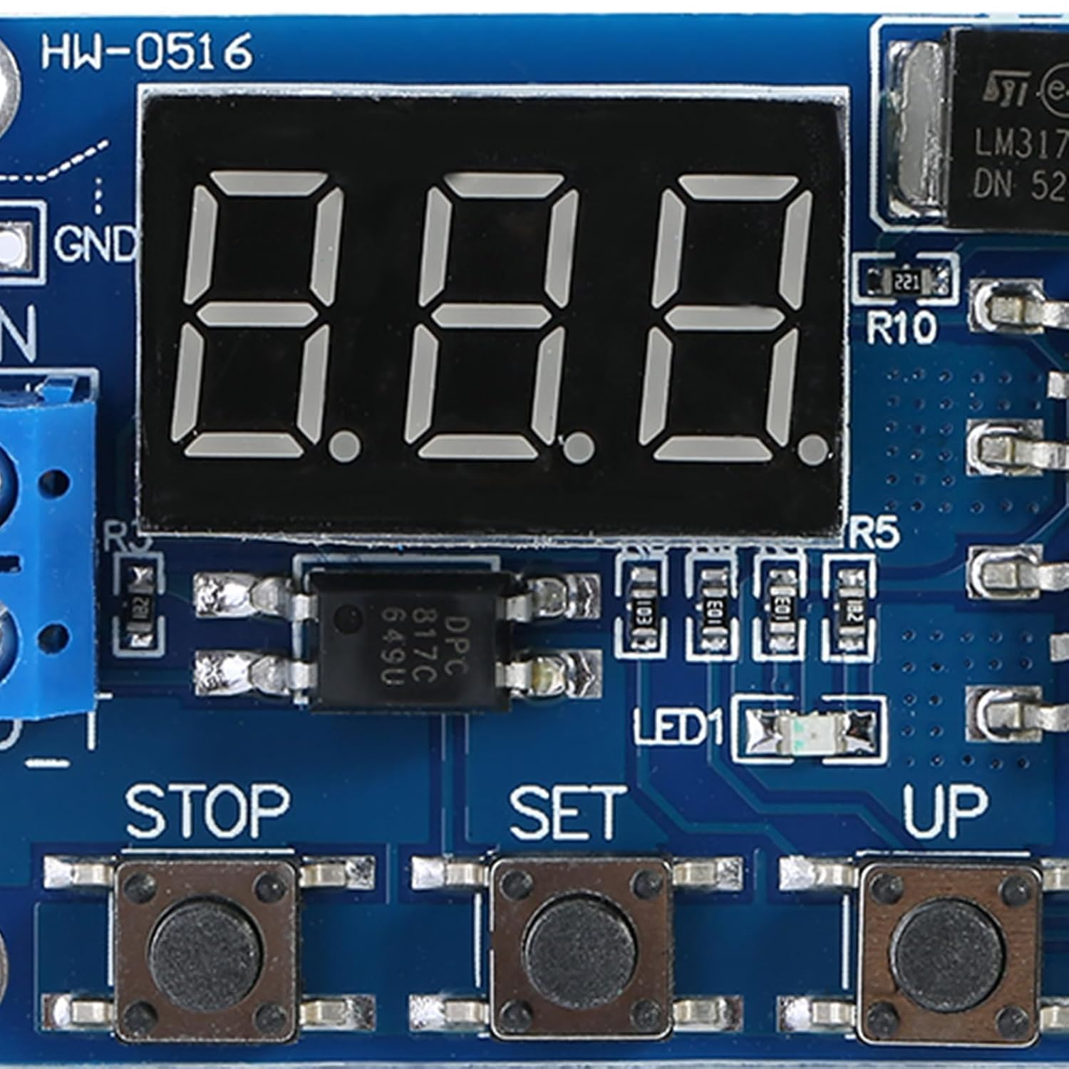
Image 5.1: Close-up view of the LED display and control buttons (STOP, SET, UP, DOWN) used for setting timing parameters and ranges.
6. Parameter Description
The following parameters are used across different operating modes:
- 'OP' - On Time: The duration for which the relay remains active (on).
- 'CL' - Off Time: The duration for which the relay remains inactive (off).
- 'LOP' - Number of Cycle Times: The number of repetitions for a cycle operation. This can be set from 1 to 999 times. '---' represents an infinite loop.
These parameters are independent of each other but are shared by each mode. For example, if you set 'OP' to 5 seconds in P1.1 mode, switching to P1.2 mode will also have its 'OP' set to 5 seconds.
In the main interface (displaying '000'), pressing the SET button will display 'OP' (or 'CL', 'LOP') and its corresponding time. If a mode only uses 'OP' time (e.g., P1.1, P1.2, P1.3), only 'OP' and its time will be displayed. For modes with 'OP', 'CL', and 'LOP' (e.g., P3.1, P3.2), pressing SET will cycle through displaying each parameter and its value.
7. How to Set Parameters
Follow these steps to configure the operating mode and parameters of your timer module:
- Determine Operating Mode: First, refer to Section 4 to identify the required operating mode for your application.
- Enter Mode Selection: Power up the module. The display will show the current work mode (P1.1 is default). Press and hold the SET button for 2 seconds to enter the mode selection interface.
- Select Mode: Use the UP and DOWN buttons to navigate and select the desired mode (P1.1 ~ P-4).
- Set Parameters: Once the mode is selected (e.g., P3.2), press the SET button. The parameter to be set will flash ('OP' on-time, 'CL' off time, 'LOP' cycles). Use the UP and DOWN buttons (press or hold) to adjust the parameter value. Then, press the STOP key to set the decimal point position, which selects the clocking range (0.1 seconds to 999 minutes). Press the SET button again to move to the next parameter for the current mode. Repeat this process for all parameters.
- Save Settings and Exit: After all parameters are set, press and hold the SET button for 2 seconds. The current mode will flash once, and then the module will return to the main interface, indicating that the parameters have been successfully saved.
Main Interface: If the relay is not in a working state, the display will show '000' without a decimal point. If it is in a working state, a decimal point will be present.
8. Specifications
Below are the technical specifications for the Hilitand DC 5V-36V Timer Module:
| Feature | Specification |
|---|---|
| Input Voltage | DC 5V-36V |
| Trigger Signal Voltage | DC 3-24V |
| Output Voltage | DC 5V-36V (matches input) |
| Maximum Current Rating | 15 A |
| Maximum Wattage | 400 W |
| Operation Mode | Automatic |
| Connector Type | Through Hole |
| Contact Type | Normally Open |
| Mounting Type | Surface Mount |
| Number of Items | 2 (per pack) |

Image 8.1: Physical dimensions of the Hilitand DC Timer Module, showing approximate length of 60mm and width of 34mm.
9. Troubleshooting
If you encounter issues with your Hilitand DC Timer Module, refer to the following troubleshooting tips:
- No Power to Module:
- Verify that the input power supply is within the DC 5V-36V range.
- Check all power wiring connections for proper polarity and secure contact.
- Ensure the power source is active and providing the correct voltage.
- Module Not Responding to Trigger:
- Confirm the trigger signal voltage is within the DC 3-24V range.
- Check the wiring to the 'SIGN' and 'GND T' terminals for secure connections.
- Review the selected operating mode (P1, P2, P3, P4) to ensure it matches your intended trigger behavior.
- Ensure the trigger signal duration is sufficient for the module to detect it.
- Timing Inaccurate:
- While generally accurate, for applications requiring extremely high precision, minor deviations (e.g., ~400ms/min) may occur. This module is suitable for most general-purpose timing tasks.
- Double-check the clocking range setting (decimal point position) and the parameter values ('OP', 'CL').
- Relay Not Activating/Deactivating as Expected:
- Verify the load is correctly wired to the 'OUT+' and 'OUT-' terminals.
- Ensure the load's voltage and current requirements do not exceed the module's maximum (DC 36V, 15A, 400W).
- Check the selected operating mode and parameter settings for any misconfigurations.
10. Maintenance
To ensure the longevity and reliable performance of your Hilitand DC Timer Module, follow these simple maintenance guidelines:
- Keep Clean and Dry: Protect the module from dust, dirt, and moisture. Use a soft, dry cloth for cleaning.
- Avoid Extreme Conditions: Do not expose the module to extreme temperatures, high humidity, or corrosive environments.
- Ensure Ventilation: If enclosed, ensure adequate airflow to prevent overheating, especially when operating at higher loads.
- Inspect Connections: Periodically check all wiring connections to ensure they remain secure and free from corrosion.
11. Warranty and Support
Hilitand is committed to providing quality products and customer satisfaction.
- Return Policy: This product is eligible for a refund or replacement within 30 days of purchase, in accordance with the seller's return policy.
- Manufacturer Support: For further assistance, technical inquiries, or to explore other Hilitand products, please visit the official Hilitand Store.
Visit the Hilitand Store on Amazon.