Xiangtat ST8
ToolkitRC ST8 Multi-Function Servo Tester User Manual
Model: ST8 | Brand: Xiangtat
1. Introduction
The ToolkitRC ST8 is a versatile multi-function servo tester and data analyzer designed for hobbyists and professionals. It is capable of testing voltage, power, current, speed, and signal data of servos. With its 4-way independent programmable signal output and support for multiple signal types (PWM, PPM, SBUS), the ST8 provides precise analysis and control for various servo applications. This manual provides essential information for the safe and effective operation of your ST8 servo tester.
2. Safety Information
Please read all safety instructions carefully before using the ToolkitRC ST8 Servo Tester.
- Ensure the input voltage is within the specified range of 7.0-28.0V. Exceeding this range can damage the device.
- When connecting servos, ensure the current draw does not exceed the specified limits for each port. For currents higher than 2A, connect to the main output interface.
- For servos requiring voltage higher than 8.4V, connect them to the main output interface, not the S1-S4 signal interfaces.
- Always verify correct polarity when connecting power sources and servos to prevent damage.
- Keep the device away from water, moisture, and extreme temperatures.
- Do not attempt to disassemble or modify the device. Refer all servicing to qualified personnel.
3. Package Contents
Upon opening the package, please verify that all items listed below are present and in good condition:
- 1x ToolkitRC ST8 Servo Tester
- 1x USB Wire
- 1x User Manual

Image: Contents of the ToolkitRC ST8 package, showing the servo tester unit, a USB cable, and the user manual.
4. Product Overview and Features
The ToolkitRC ST8 is designed for comprehensive servo analysis and testing. Key features include:
- Multi-Function Data Analyzer: Capable of testing voltage, power, current, speed, and signal data of servos.
- 4-Way Independent Programmable Signal: Provides 8-channel signal output with 1us precision.
- Independent Current Data Collection: 4-way independent current data acquisition displayed graphically.
- Multiple Data Testing: Supports testing of speed, linear data, steps, and more.
- Multiple Signal Types: Compatible with PWM, PPM, and SBUS signals, with 1us precision.
- Wide Input Voltage Range: Supports input voltage up to 28V, suitable for testing HV (High Voltage) servos.
- High Load Capacity: Maximum load capacity of up to 100W.
- Multi-Language System: User-selectable language options.
- USB Firmware Update: Easy firmware updates via USB 3.0.
- Display: 2.4" TFT RGB LCD Screen (320*240 resolution).

Image: The ToolkitRC ST8 Servo Tester showing its 2.4-inch LCD screen with the setup menu, including options for voltage output, cycle count, and language settings.
5. Device Layout and Connections
Familiarize yourself with the various ports and controls on the ST8 servo tester:

Image: Labeled diagram of the ToolkitRC ST8, highlighting the XT60 Input (7-28V@MAX 10A), XT60 Output (5.0-28.0V@MAX 10A), S1-S4 Signal Port (5.0-8.4V@MAX 4A), S4 EXT Signal Port (5.0-8.4V@MAX 4A), S5 Signal Port (Input PWM/PPM/SBUS), MicroUSB 3.0 port, P1 Knobs, and the OK/EXIT buttons.
- XT60 Input: For connecting the 7-28V power supply (Max 10A).
- XT60 Output: Main power output (5.0-28.0V, Max 10A). Use this for high current/voltage servos.
- S1-S4 Signal Ports: Individual signal output ports (5.0-8.4V, Max 4A).
- S4 EXT Signal Port: Extended signal port (5.0-8.4V, Max 4A).
- S5 Signal Port: Input for PWM/PPM/SBUS signals.
- MicroUSB 3.0: For firmware updates.
- P1 Knobs: For adjusting parameters (1000-2000us).
- OK Button: Used for confirmation and long-press for system settings.
- EXIT Button: Used to exit menus or stop testing.
6. Setup
Follow these steps to set up your ToolkitRC ST8 Servo Tester:
- Connect Power Supply: Connect a 7-28V DC power supply to the XT60 Input port. Ensure correct polarity.
- Power On: After connecting power, the LCD screen will display the ToolkitRC logo for approximately 2 seconds, accompanied by a startup sound.
- Connect Servos:
- For standard servos (up to 2A current, up to 8.4V), connect them to the S1-S4 signal ports.
- For high current (over 2A) or high voltage (over 8.4V) servos, connect them to the main XT60 Output port for power, and their signal wire to the appropriate S1-S4 signal port.

Image: The ToolkitRC ST8 Servo Tester demonstrating a typical setup, connected to a battery pack for power and multiple servos for testing, illustrating its multi-channel capability.
7. Operating Instructions
The ST8 offers various testing modes and settings. Here are the basic operating steps:
- Initial Test (PWM Signal): After power-on, press the "EXIT" button to enter the PWM signal test mode.
- Channel Selection: Rotate the "OK" button (knob) to select different channels (S1-S4, S5). Press "OK" to confirm your selection.
- Adjusting Parameters: Use the P1 knob to adjust signal parameters (e.g., pulse width for PWM).
- System Settings: To access system settings, long-press the "OK" button for 2 seconds. This menu allows you to configure options like voltage output, cycle count, language, and theme style.
- Exiting Settings: Press the "EXIT" button to leave the system settings menu.
- Signal Type Selection (S5 Port): When using the S5 port, the device supports PWM, PPM, and SBUS signal types. The display will indicate the active signal type.

Image: The ToolkitRC ST8 display showing a real-time graph of servo signal output, along with input voltage and output parameters, demonstrating its data analysis capabilities.
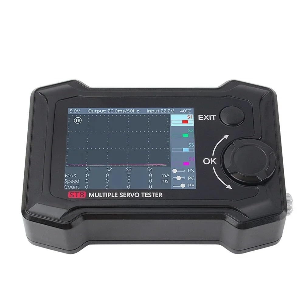
Image: The ToolkitRC ST8 display showing a real-time graph of servo signal output, along with input voltage and output parameters, demonstrating its data analysis capabilities.
8. Specifications
| Parameter | Value |
|---|---|
| Channel Output | 8CH |
| Max Load | 100W |
| Input Voltage | 7.0-28.0V @ MAX 10A |
| Main Output Voltage | 5.0-28.0V @ MAX 10A |
| Signal Output Voltage (S1-S4) | 5.0-8.4V @ MAX 2A |
| Signal Output Voltage (S4 EXT) | 5.0-8.4V @ MAX 4A |
| PWM Signal Output (S1-S4) | 100us-2900us @ 33-1000Hz |
| PWM Signal Output (S5) | 500us-2500us |
| PPM Signal Output (S5) | 8CH |
| SBUS Signal Output (S5) | 16CH |
| P1 Button Range | 1000-2000us |
| Micro USB | Update @ USB3.0 |
| Display | 2.4" TFT RGB LCD Screen (320*240 resolution) |
| Product Size | 96*68*26mm (Approx.) |
| Net Weight | 140g (Approx.) |
| Manufacturer | Xiangtat |
| ASIN | B0CYZRFT4V |
| UPC | 716198752262 |
9. Maintenance
- Keep the device clean by wiping it with a soft, dry cloth. Avoid using harsh chemicals or abrasive materials.
- Store the servo tester in a dry, cool place, away from direct sunlight and extreme temperatures.
- Regularly check all connections for wear or damage.
- Ensure the USB port is free from dust and debris, especially before firmware updates.
10. Troubleshooting
If you encounter issues with your ToolkitRC ST8, consider the following common solutions:
- Device does not power on:
- Verify the power supply is connected correctly to the XT60 Input.
- Ensure the input voltage is within the 7-28V range.
- Check the power cable for any damage.
- Servo not responding:
- Confirm the servo is correctly connected to the signal port (S1-S4 or S5) and receiving adequate power.
- Check the servo's specifications to ensure compatibility with the output voltage and signal type.
- Test with a different servo to rule out a faulty servo.
- Incorrect readings or erratic behavior:
- Ensure all connections are secure and free from interference.
- Check for any loose wires or damaged connectors.
- Consider performing a firmware update if available, as this can resolve software-related issues.
11. Warranty and Support
For warranty information and technical support, please refer to the documentation provided with your purchase or contact the manufacturer, Xiangtat, directly. Specific warranty terms may vary by region and retailer.
For the latest firmware updates and additional resources, please visit the official ToolkitRC website or contact their support channels.
Ask a question about this manual
Ask about setup, troubleshooting, compatibility, parts, safety, or missing instructions. Manuals+ will review the question and use this page’s manual context to help answer it.