1. Introduction
This manual provides detailed instructions for the DROK 200735_JPN DC-DC Step-Up/Step-Down Converter Module. This versatile module is designed to provide stable power output with adjustable voltage and current, suitable for a wide range of applications including laboratory testing, industrial control, and DIY projects. Please read this manual thoroughly before operation to ensure safe and correct usage.
2. Product Features
- Wide Input/Output Range: Supports DC 6-36V input and adjustable DC 0.5-36V output with 0-4.5A adjustable output current. Maximum output power is 40W.
- Enhanced Cooling System: Features a dedicated 5V fan port for optional 30mm fan installation (fan not included) to improve heat dissipation.
- Multi-functional Interface: Equipped with a built-in buzzer for key operation feedback and warning alerts, ensuring quick recognition of operations and potential issues.
- Comprehensive Protection: Includes anti-reverse connection, anti-reverse flow, under-voltage, over-voltage, over-current, over-temperature, and over-power protection for safe and reliable operation.
- LVP Protection: Low Voltage Protection (LVP) activates when input voltage is insufficient. Increase input voltage until the product operates normally.
- Smart Temperature Control: The fan port supports smart temperature control, activating only when current is high and temperature rises.
3. Product Dimensions and Overview
The following image illustrates the physical dimensions and key components of the converter module.
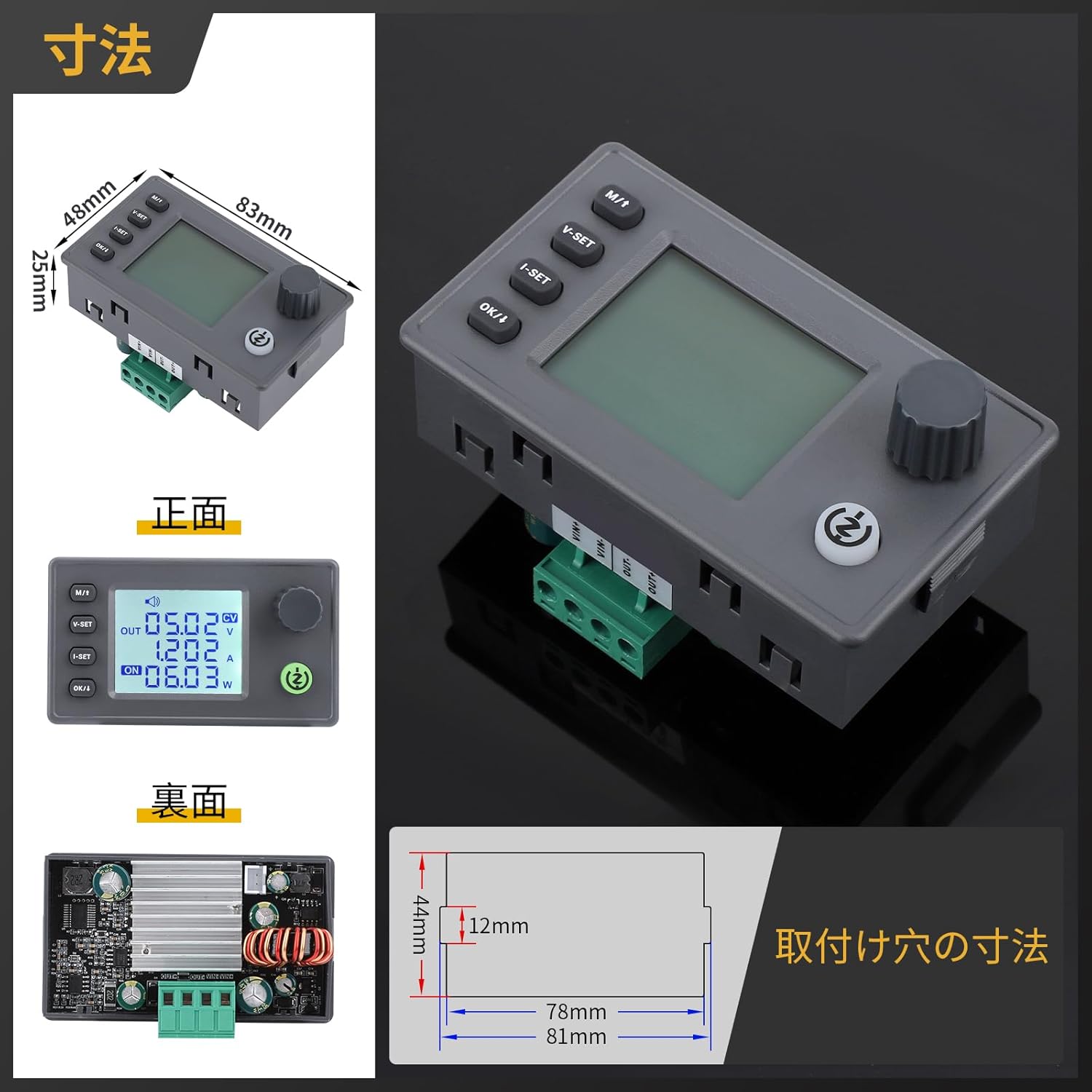
Image: Front, back, and side views with dimensions (83mm x 48mm x 29.4mm) and mounting hole details.
4. Technical Specifications
Detailed technical parameters of the DROK 200735_JPN module are provided below.
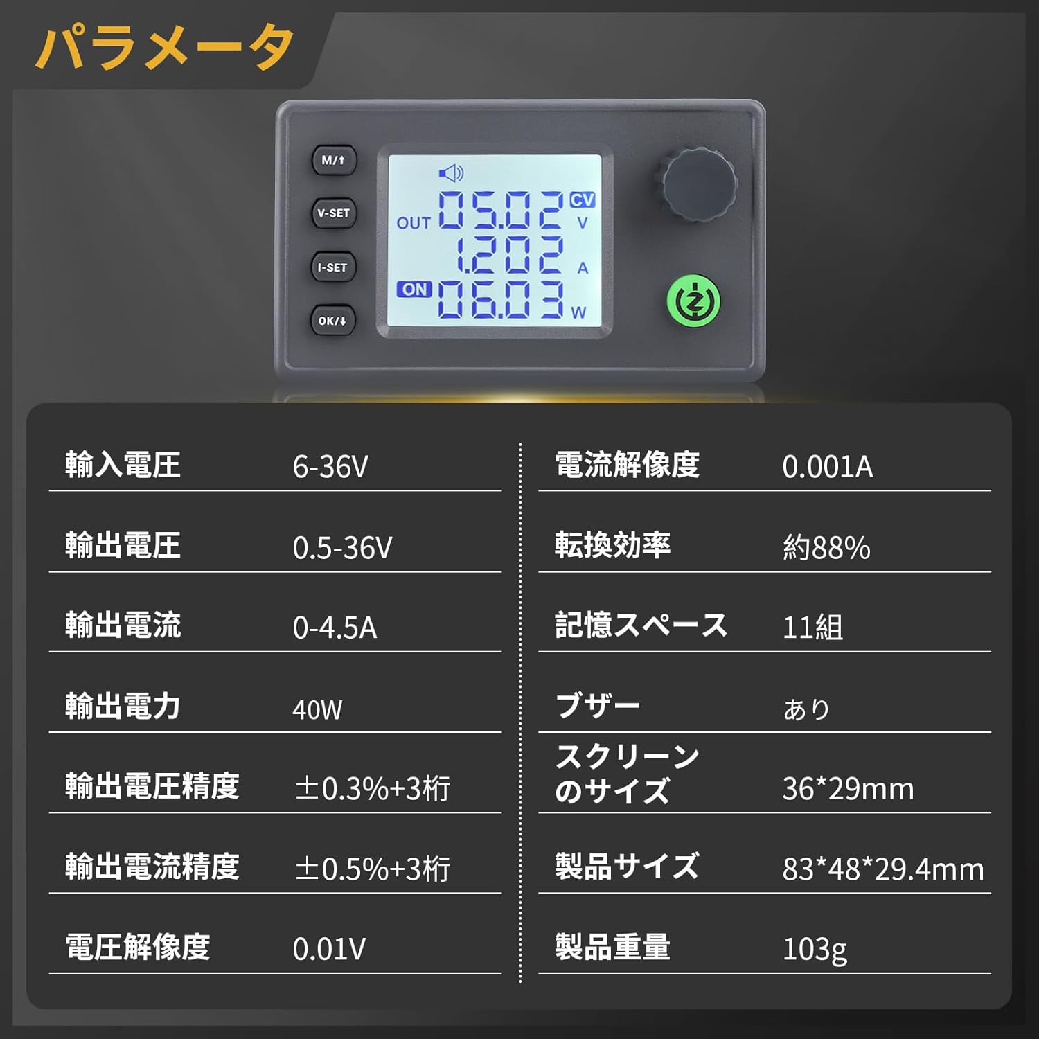
Image: Table of technical parameters including input/output voltage, current, power, and display size.
| Parameter | Value |
|---|---|
| Input Voltage Range | DC 6-36V |
| Output Voltage Range | DC 0.5-36V |
| Output Current Range | 0-4.5A |
| Output Power | 40W |
| Voltage Resolution | 0.01V |
| Current Resolution | 0.001A |
| Voltage Display Accuracy | ±0.3% + 3 digits |
| Current Display Accuracy | ±0.5% + 3 digits |
| Conversion Efficiency | Approx. 88% |
| Memory Spaces | 11 groups |
| Buzzer | Included |
| Screen Size | 36 x 29 mm |
| Product Size | 83 x 48 x 29.4 mm |
| Product Weight | 103g |
5. Setup and Connections
Before operating the module, ensure proper connections for input and output. The module features plug-in terminals for easy installation and replacement.

Image: Internal view showing the buzzer, 5V fan port, and plug-in terminals for easy connection.
- Input Power: Connect your DC 6-36V power source to the input terminals (IN+ and IN-). Ensure correct polarity.
- Output Load: Connect your load to the output terminals (OUT+ and OUT-).
- Optional Fan: If additional cooling is required, connect a 30mm 5V fan (max 150mA) to the dedicated fan port. The fan is temperature-controlled and will activate automatically when needed.
6. Operating Instructions
The module features an LCD display and intuitive buttons for setting voltage, current, and monitoring parameters.

Image: Detailed view of the LCD display showing input voltage, output voltage, output current, power, energy, time, and temperature.

Image: Explanation of button functions for voltage setting, current setting, display switching, and output control.
6.1. Button Functions
- M/1 Button:
Short press: Switch between input voltage and output voltage display.
Long press: Enter or exit the setting menu. - V-SET Button:
Short press: Adjust voltage setting. - I-SET Button:
Short press: Adjust current setting. - OK/↓ Button:
Short press: Switch display of output power (W), capacity (Ah), energy (Wh), time (h), and temperature (°C).
Long press: Toggle output ON/OFF. - Rotary Encoder:
Short press: Enable/disable lock function.
Long press: Enter setting menu (similar to M/1 long press).
Rotate left: Decrease numerical value.
Rotate right: Increase numerical value.
6.2. Adjusting Voltage and Current
Use the V-SET and I-SET buttons in conjunction with the rotary encoder to set the desired output voltage and current. The LCD will display the current settings. The device will maintain the default values even after restarting.
Video: How to adjust voltage and current
This video demonstrates the process of adjusting the output voltage and current settings on a similar DC power supply module.
6.3. Data Logging and Control
The module can be programmed and controlled via computer software, allowing for data logging and analysis. This feature enables users to record and save data to Excel sheets for convenient analysis.
Video: Step-up/down converter automatic step-up/down board
This video showcases the functionality of an automatic step-up/down converter board, including its display and control features, which are similar to the DROK module.
7. Safety Precautions and Protection Features
The DROK converter module is equipped with multiple protection functions to ensure safe operation. Always adhere to these guidelines to prevent damage to the device or connected equipment.
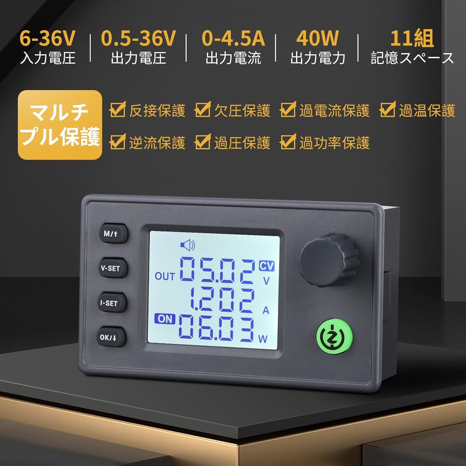
Image: Overview of the multi-protection features including reverse connection, under-voltage, over-current, over-temperature, anti-reverse flow, over-voltage, and over-power protection.
- Anti-Reverse Connection Protection: Prevents damage if input polarity is reversed.
- Anti-Reverse Flow Protection: Protects the input power source from current flowing back from the output.
- Under-Voltage Protection (LVP): Automatically cuts off output if the input voltage drops below a safe threshold. Increase input voltage to resolve.
- Over-Voltage Protection (OVP): Shuts down output if the output voltage exceeds the set limit.
- Over-Current Protection (OCP): Disables output if the output current surpasses the set limit.
- Over-Temperature Protection (OTP): Activates if the module's internal temperature becomes too high, reducing power or shutting down to prevent damage.
- Over-Power Protection (OPP): Limits output power to prevent exceeding the module's maximum capacity.
Always ensure that the input voltage and current are within the specified ranges to avoid triggering protection mechanisms or damaging the module.
8. Troubleshooting
- No Output/Low Output Voltage: Check input power supply for sufficient voltage and current. Verify output connections and load. Ensure LVP is not active (increase input voltage if necessary).
- Module Overheating: Ensure adequate ventilation. Consider installing a 30mm 5V fan to the dedicated port if operating at higher loads or in warm environments.
- Display Issues: Check power connections. If the display is unresponsive, try power cycling the module.
- Protection Activated: If any protection (OVP, OCP, OTP, OPP) is triggered, identify and resolve the underlying cause (e.g., reduce load, check for short circuits, ensure proper cooling) before resuming operation.
9. Maintenance
To ensure the longevity and optimal performance of your DROK converter module:
- Keep the module clean and free from dust and debris.
- Avoid exposing the module to moisture or extreme temperatures.
- Regularly check connections for tightness and signs of wear.
- Do not attempt to disassemble or modify the module, as this may void the warranty and cause damage.
10. Warranty and Support
For warranty information, technical support, or any questions regarding your DROK 200735_JPN DC-DC Step-Up/Step-Down Converter Module, please refer to the seller's contact information or visit the official DROK website. Keep your purchase receipt as proof of purchase for warranty claims.