1. Introduction
This manual provides essential information for the safe and effective use of the FRPKPNOX HFD27 Series Mini DIP Relays. These sensitive electromechanical relays are designed for various electronic applications requiring switching capabilities for DC and AC loads. Please read this manual thoroughly before installation and operation.
2. Product Overview
The FRPKPNOX HFD27 series consists of compact, 8-pin Dual In-line Package (DIP) relays. These relays are designed for printed circuit board (PCB) mounting and offer reliable switching for low-power applications. Available in various coil voltages, they provide electrical isolation between the control circuit and the load circuit.
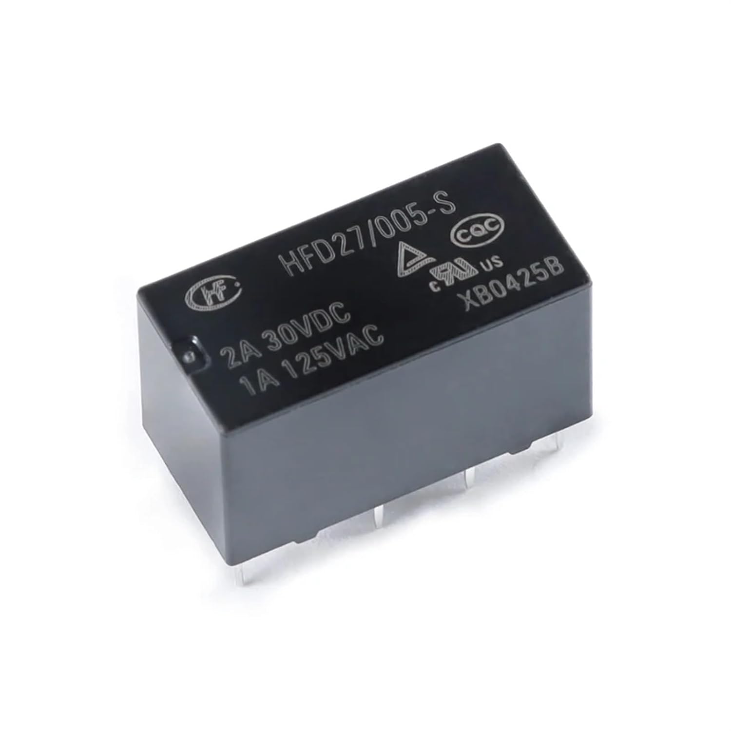
Figure 2.1: FRPKPNOX HFD27-005-S Mini DIP Relay. This image shows a single HFD27-005-S relay, highlighting its compact form factor and pin configuration. The markings indicate a 2A 30VDC and 1A 125VAC contact rating.
Key features include:
- Compact DIP package for PCB mounting.
- Available coil voltages: 5V DC (HFD27-005-S), 12V DC (HFD27-012-S), 24V DC (HFD27-024-S).
- Sensitive coil for low power consumption.
- Electromechanical switching for robust performance.

Figure 2.2: FRPKPNOX HFD27 Series Relays. This image displays the three main variants of the HFD27 series: HFD27-005-S, HFD27-012-S, and HFD27-024-S, illustrating their identical physical dimensions despite different coil voltages.
3. Specifications
| Feature | Description |
|---|---|
| Model Series | HFD27 |
| Coil Voltage Options | 5V DC (HFD27-005-S), 12V DC (HFD27-012-S), 24V DC (HFD27-024-S) |
| Contact Configuration | Single Pole Double Throw (SPDT) - 1 Form C (implied by 8-pin DIP for mini relays) |
| Contact Rating (DC) | 2A @ 30V DC |
| Contact Rating (AC) | 1A @ 125V AC |
| Pin Configuration | 8-Pin DIP (Dual In-line Package) |
| Dimensions (Approx.) | 1.18 x 0.79 x 0.39 inches (30 x 20 x 10 mm) |
| Weight (Approx.) | 1.76 ounces (50 grams) |
| Manufacturer | FRPKPNOX |

Figure 3.1: Bottom view of the HFD27 Relay. This image illustrates the 8-pin DIP configuration, crucial for proper PCB mounting and connection.
4. Installation and Setup
The HFD27 series relays are designed for through-hole mounting on Printed Circuit Boards (PCBs). Proper installation is crucial for reliable operation.
- Identify Pins: Refer to the relay's datasheet (not provided here, but generally available from manufacturer) for the exact pinout. Typically, two pins are for the coil, and the remaining pins are for the contacts (Common, Normally Open (NO), Normally Closed (NC)).
- PCB Preparation: Ensure the PCB has correctly sized holes and pads for the 8 DIP pins.
- Insertion: Carefully insert the relay pins into the corresponding holes on the PCB. Ensure the relay is oriented correctly, as indicated by any notch or dot on the relay body.
- Soldering: Solder each pin securely to the PCB. Use appropriate soldering techniques to prevent cold joints or solder bridges. Avoid excessive heat to prevent damage to the relay.
- Coil Connection: Connect the relay coil to the appropriate DC voltage source (5V, 12V, or 24V) matching the specific relay model (e.g., HFD27-005-S requires 5V DC). Ensure correct polarity if the coil is polarized (though many small signal relays are not).
- Load Connection: Connect the load circuit to the relay's contact pins. The common (COM) pin connects to one side of the load, and the normally open (NO) or normally closed (NC) pin connects to the other side, depending on the desired switching behavior.
Note: Always ensure the power supply to the circuit is disconnected before performing any installation or wiring.
5. Operation
The HFD27 series relays operate by energizing an internal coil, which creates a magnetic field to actuate mechanical contacts. This allows a low-power control signal to switch a higher-power load.
- Coil Activation: When the rated DC voltage (5V, 12V, or 24V, depending on the model) is applied across the coil pins, the coil energizes.
- Contact Switching: Upon coil energization, the common (COM) contact switches from the normally closed (NC) position to the normally open (NO) position. When the coil voltage is removed, the contacts return to their original (NC) state.
- Load Control: The load connected to the NO contacts will be switched ON when the coil is energized, and OFF when de-energized. Conversely, a load connected to the NC contacts will be OFF when the coil is energized and ON when de-energized.
Ensure that the load current and voltage do not exceed the relay's contact ratings (2A 30VDC, 1A 125VAC) to prevent damage to the relay and ensure safe operation.
6. Maintenance
FRPKPNOX HFD27 series relays are generally maintenance-free due to their sealed construction. However, adhering to the following guidelines can help ensure longevity:
- Keep Clean: Ensure the relay and surrounding PCB area are free from dust, dirt, and moisture.
- Inspect Connections: Periodically check solder joints and wiring for any signs of corrosion, looseness, or damage.
- Environmental Conditions: Operate the relay within its specified temperature and humidity ranges to prevent premature failure.
- Avoid Overloading: Never exceed the specified contact current and voltage ratings. Overloading can cause contact welding or premature wear.
7. Troubleshooting
If the relay is not functioning as expected, consider the following troubleshooting steps:
| Problem | Possible Cause | Solution |
|---|---|---|
| Relay coil does not energize. | Incorrect coil voltage, no power to coil, faulty wiring, damaged coil. | Verify coil voltage matches relay model (5V, 12V, or 24V). Check power supply and wiring connections. Test coil resistance with a multimeter. |
| Relay clicks but contacts do not switch load. | Load wiring error, open circuit in load, contacts welded/damaged. | Check load circuit wiring. Verify load is functional. If contacts are suspected to be damaged, replace the relay. |
| Relay contacts remain stuck (open or closed). | Contact welding due to overload, mechanical failure. | Ensure load current and voltage are within specifications. Replace the relay if contacts are welded or mechanically stuck. |
| Intermittent operation. | Loose connections, fluctuating coil voltage, environmental factors. | Inspect all solder joints and wiring. Ensure stable coil voltage. Check for excessive vibration or temperature fluctuations. |
If issues persist after troubleshooting, consider consulting a qualified technician or replacing the relay.
8. Safety Information
Adhere to the following safety precautions to prevent injury and damage to equipment:
- Always disconnect power to the circuit before installing, wiring, or servicing the relay.
- Ensure that the coil voltage applied matches the relay's rated coil voltage.
- Do not exceed the maximum contact current and voltage ratings.
- Avoid touching live electrical components.
- Install relays in an environment free from excessive moisture, dust, corrosive gases, and extreme temperatures.
- If you are not confident in your ability to safely install or troubleshoot electrical components, seek professional assistance.
9. Warranty and Support
For warranty information or technical support regarding your FRPKPNOX HFD27 series relay, please refer to the product packaging or contact your point of purchase. Keep your purchase receipt as proof of purchase.