1. Introduction
The 100BALANCE BMS (Battery Management System) is an intelligent active balance battery protection board designed for Li-ion, LiFePO4, and LTO lithium battery packs. It provides comprehensive protection and management to ensure the safety and longevity of your battery system. This manual provides detailed instructions for installation, operation, and maintenance.
Key Features:
- Enhanced Battery Safety: Offers protection against overcharging, over-discharging, overcurrent, short circuits, and extreme temperatures.
- Extra Protection Features: Includes pre-charge protection, wrong connection/missing connection detection, parallel connection current limiting, and cell balancing.
- Smart Battery Management: Manage your battery easily with the Android or iOS mobile app. Bluetooth connectivity allows you to monitor status, adjust settings, and control charge/discharge from your device.
- Active Balancing: Features continuous 1A active balancing current for efficient cell equalization.
- Wide Voltage Compatibility: Compatible with 8S-24S battery packs, supporting 24V, 36V, 48V, 60V, 72V, and 84V systems.
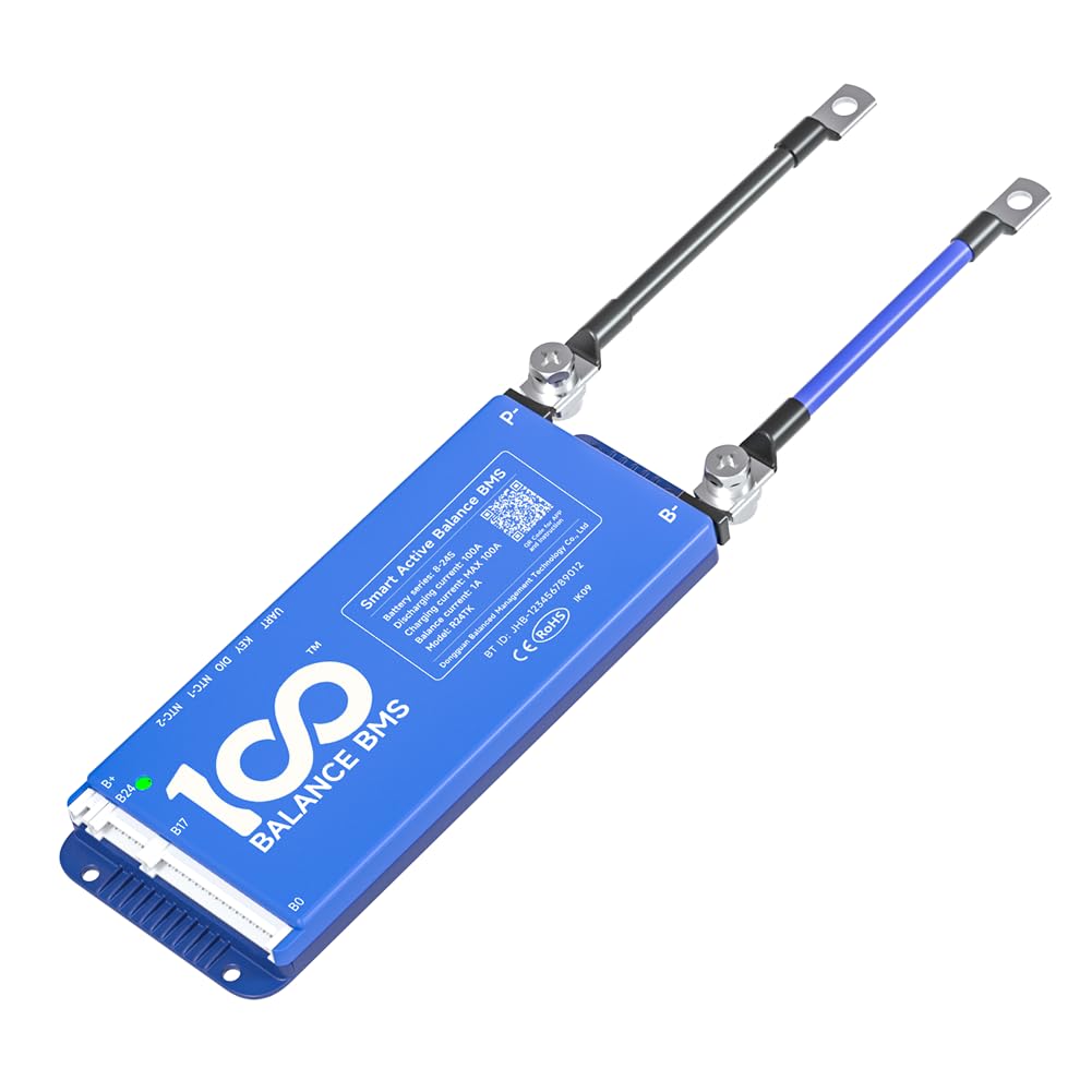
Figure 1: 100BALANCE BMS 150A Active Balance 8S-24S Smart Battery Protection Board.
2. Specifications
General Specifications:
| Attribute | Value |
|---|---|
| Brand | 100 BALANCE |
| Model Number | 100BALANCE 150A 8S-24S |
| Item Weight | 1.1 Pounds |
| Input Voltage | 100 Volts |
| Plug Format/Type | Type B |
| Manufacturer | Dongguan Balanced Management Technology Co., Ltd |
| Warranty | 1 year |
Performance Parameters:
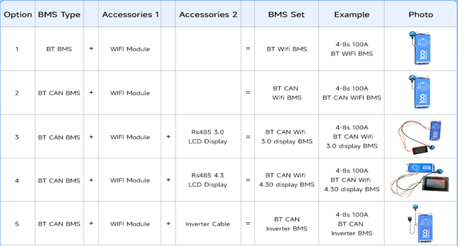
Figure 2: Basic specifications of the BMS.
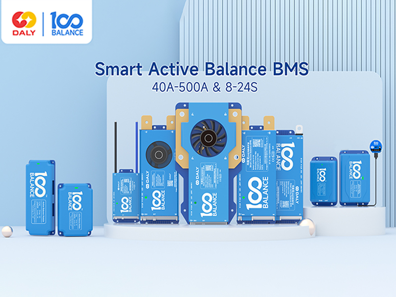
Figure 3: Current parameter correspondence table for various models.

Figure 4: Product dimensions and battery compatibility details.
3. Package Contents
The standard package for the 100BALANCE BMS includes the following items:
- Smart active balance BMS (x1)
- P-&B- cable (x1)
- Sampling cable (x1)
- B+ cable (x1)
- NTC (x1)
- Key switch cable (x1)
- Screws (x2)
- User Manual (x1)
- Packaging box (x1)
Note: RS485/CAN port cable and WiFi Module are standard only for BT RS485/CAN version BMS.

Figure 5: Contents included in the 100BALANCE BMS package.
4. Setup and Wiring Installation
Proper wiring is crucial for the safe and correct operation of the BMS. Please follow these instructions carefully.
Wiring Steps:
- Prepare Battery Pack: Ensure your battery pack is assembled with total positive and total negative terminals clearly identified.
- Connect B- and P- Cables: Connect the black B- cable to the total negative terminal of the battery pack. Connect the red P- cable to the positive terminal of the first string.
- Connect Sampling Wires: Carefully connect the sampling wires to each cell in the correct sequence, starting from B0 (negative) to B+ (positive). Ensure each wire is soldered securely.
- Seal Excess Cables: If using a BMS with fewer strings than the maximum supported (e.g., 8S BMS with a 17S sampling cable), seal any unused sampling cables with insulation tape to prevent short circuits.
- Verify Voltage: Use a multimeter to measure the voltage across the wiring harness to ensure consistency and correctness before plugging into the BMS.
- Connect NTC Cable: Plug the NTC (Negative Temperature Coefficient) cable into the NTC-A port on the BMS.
- Connect Sampling Harness to BMS: Insert the sampling wire harness into the designated port on the BMS.
Important: Miswiring protection is limited to 6 strings. Connecting more than 6 strings incorrectly can damage your BMS. Always follow the wiring sequence strictly. If the wiring sequence is reversed, it will lead to BMS damage.

Figure 6: General wiring diagram for the BMS.

Figure 7: Close-up view of BMS wiring connections.
Video 1: This video provides an introduction to the 100BALANCE Smart Active Balance BMS and demonstrates the wiring process for battery packs.
5. Operation
The 100BALANCE BMS offers multiple ways to monitor and manage your battery pack, including a mobile app and PC host software.
5.1 Mobile App Operation
The mobile app allows for convenient monitoring and parameter adjustment via Bluetooth. Download the 'Balance BMS' app from your device's app store. Once installed, connect to your BMS via Bluetooth to view real-time battery data, including total voltage, current, temperature, SOC (State of Charge), cell voltages, and alarm information. You can also adjust various protection parameters and balancing settings.
5.2 PC Host Software Operation
For more detailed monitoring and advanced settings, use the PC host software. This requires a UART, RS485, or CAN communication cable (depending on your BMS version and accessories).
- Download PC Host Software: Visit the official 100BALANCE website or contact customer service for the PC host software and necessary drivers (UART/RS485/CAN).
- Connect BMS to PC: Connect the appropriate communication cable (e.g., UART cable) from the BMS to your PC.
- Launch Software: Open the PC host software. Select the correct communication port (COM port for UART/RS485, or CAN settings) and baud rate (e.g., 9600 for UART/RS485, 250 for CAN).
- Monitor Data: The 'Live Data' screen displays real-time battery information.
- Set Parameters: Access the 'Set Param' page to modify balance current, sleep time, rated capacity, and protection parameters. You may need to enter a default password (e.g., 20211115) to enter management mode.
- Engineering Interface: The 'Engineering' interface allows for current calibration to improve data accuracy and control various switches (charge, discharge, fan).
- History Data: View battery alarm information on the 'His Data' page. You can read historical faults and clear history data.
- BMS Upgrade: Use the 'BMS Upgrade' section to update the BMS firmware by loading the upgrade file and starting the process.
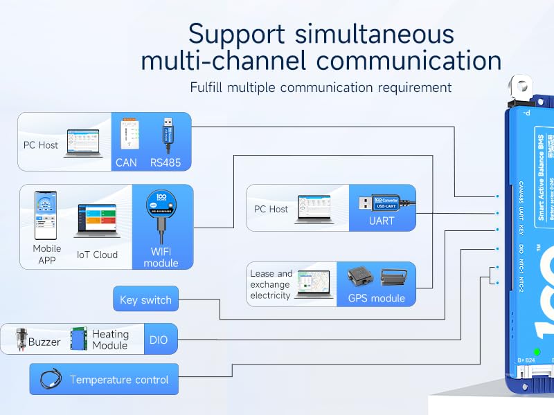
Figure 8: BMS supports simultaneous multi-channel communication including Mobile APP, PC Host, IoT Cloud, WiFi, GPS, and various modules.
Video 2: This video demonstrates how to connect the 100BALANCE Smart BMS to the PC host software and navigate its interface.
6. Optional Accessories
The 100BALANCE BMS supports various optional accessories to extend its functionality:
- UART Cable: For PC connection and communication.
- RS485 Cable: For PC connection and communication, often used for longer distances or industrial applications.
- CAN BUS: For PC connection and communication, commonly used in automotive and industrial control systems.
- WiFi Module: Enables remote monitoring and control via IoT cloud.
- LCD Display (3.0 inch / 4.3 inch Touch Display): Provides real-time battery information and allows parameter changes directly on the display.
- Heating Module: Used in cold environments to pre-heat the battery pack, ensuring optimal performance.
- Key Switch Button: Can be used to switch the discharge MOSFET on and off.
- Inverter Connection Line: For direct connection to compatible inverters.
- Parallel Interface Board / Parallel Module: For managing parallel battery pack configurations.

Figure 9: Various optional accessories for the 100BALANCE BMS.
7. Maintenance
To ensure the longevity and optimal performance of your 100BALANCE BMS, follow these maintenance guidelines:
- Regular Inspection: Periodically check all wiring connections for tightness and signs of corrosion or damage.
- Keep Clean: Ensure the BMS unit is free from dust, dirt, and moisture. Use a dry, soft cloth for cleaning.
- Environmental Conditions: Operate the BMS within its specified temperature range (-40°C to 85°C). Avoid exposure to extreme temperatures or humidity.
- Firmware Updates: Regularly check for and install any available firmware updates for the BMS to ensure you have the latest features and bug fixes.
8. Troubleshooting
If you encounter issues with your 100BALANCE BMS, consider the following:
- No Power/No Indication: Check all power connections and ensure the battery pack is providing sufficient voltage. Verify the BMS is correctly wired to the battery.
- BMS Not Connecting to App/PC Host: Ensure Bluetooth is enabled on your mobile device or the communication cable is securely connected to the PC. For PC host, verify correct COM port and baud rate settings.
- Alarm Indications: Refer to the mobile app or PC host software's 'Alarm List' or 'History Data' section for specific fault codes and descriptions. Common alarms include over-voltage, under-voltage, over-current, and temperature warnings.
- Balancing Issues: If cells are not balancing, check the 'Set Param' page in the app/PC host to ensure balancing is enabled and the voltage difference threshold is correctly set. The minimum current that can be displayed is 0.1A. Balancing open conditions are triggered when cells reach the open voltage and there is a voltage difference (default 0.01V).
- Battery Pack Parallel Connection: When paralleling lithium battery packs, ensure the voltage difference between packs is less than 1 volt to prevent the BMS from triggering short circuit protection by high current. Manually disconnect the discharging MOS in the Bluetooth APP or PC software to prevent battery packs from firing during parallel connection.
- SOC Calibration: For 100% SOC calibration, when single cell overvoltage protection level 2 is triggered, the BMS will be calibrated to 100% SOC.
9. Safety Precautions
Always observe the following safety precautions when installing, operating, or maintaining the BMS:
- Professional Installation: Installation should ideally be performed by qualified personnel.
- Correct Wiring: Strictly follow the wiring diagrams and sequences provided in this manual. Incorrect wiring can lead to severe damage to the BMS, battery pack, or personal injury.
- Voltage Compatibility: Ensure the BMS model is compatible with your battery pack's cell count (S-number) and voltage.
- Avoid Short Circuits: Take extreme care to prevent short circuits during wiring and operation. Use insulated tools.
- Environmental Protection: Do not expose the BMS to water, fire, or corrosive substances.
- Emergency Procedures: In case of smoke, fire, or unusual odors, immediately disconnect the battery pack if safe to do so and evacuate the area.
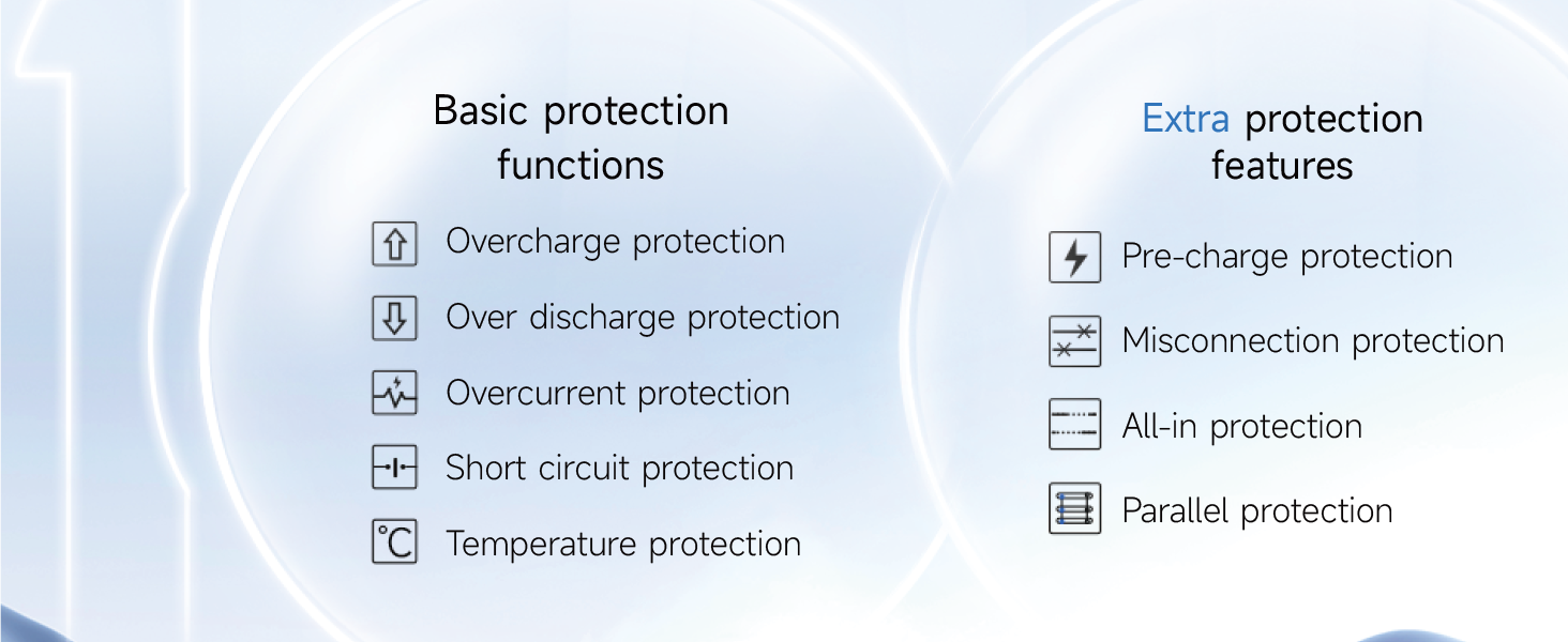
Figure 10: Overview of basic and extra protection functions provided by the BMS.
10. Warranty and Support
The 100BALANCE BMS 150A 8S-24S comes with a 1-year warranty from the date of purchase, covering manufacturing defects. This warranty does not cover damage caused by improper installation, misuse, unauthorized modifications, or external factors.
For technical support, warranty claims, or further inquiries, please refer to the contact information provided with your product packaging or visit the official 100BALANCE website.