
HUAREW HWX-W3230
HUAREW W3230 Digital Temperature Controller User Manual
Model: HWX-W3230
1. Product Overview
The HUAREW W3230 Digital Temperature Controller is a versatile instrument designed for precise temperature regulation in various applications. It features a clear LED display, an NTC temperature probe, and supports both heating and cooling modes. This manual provides detailed instructions for its installation, operation, and maintenance.
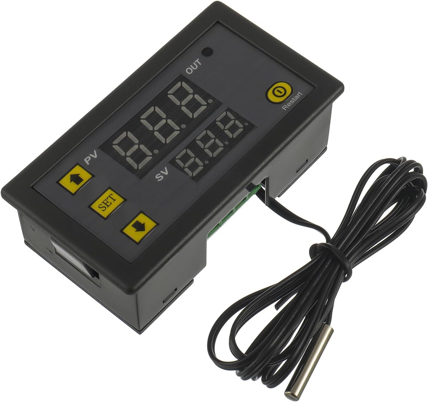
Image 1.1: Front view of the HUAREW W3230 Digital Temperature Controller with its NTC temperature probe.
Key Features:
- Wide temperature control range: -50℃ to 120℃.
- High control accuracy: 0.1℃.
- Dual working modes: Heating (H) and Cooling (C).
- Equipped with a 1-meter NTC10K waterproof stainless steel probe.
- Durable ABS material construction.
- LED indicator for output status.
2. Product Specifications

Image 2.1: Detailed specifications of the W3230 Temperature Controller.
| Parameter | Value |
|---|---|
| Model | HWX-W3230 |
| Power Supply | 220V AC (also available in 12V DC versions, check product label) |
| Temperature Control Range | -50℃ to 120℃ |
| Control Accuracy | 0.1℃ |
| Measurement Input | NTC10K (1M Waterproof Probe) |
| Output Capacity | 1 channel relay output, 20A |
| Environmental Requirements | Temperature: -10℃ to 60℃, Humidity: 20% to 85% RH |
| Material | ABS |
| Dimensions | 79mm x 45mm x 27mm (approx. 3.11 x 1.77 x 1.06 inches) |
| Item Weight | Approx. 50g (1.76 ounces) |

Image 2.2: Physical dimensions of the W3230 Temperature Controller.
3. Installation and Wiring
Proper installation and wiring are crucial for the safe and correct operation of the W3230 temperature controller. Ensure all power is disconnected before proceeding with wiring.
3.1 Wiring Diagram

Image 3.1: Basic wiring diagram for the W3230 Temperature Controller.
The controller has four terminals for connection:
- +VCC: Positive power input for the controller (e.g., 220V AC Live or 12V DC Positive).
- -GND: Negative power input for the controller (e.g., 220V AC Neutral or 12V DC Negative).
- S1, S2: Relay output terminals. These are dry contacts (isolated) and can be used to control an external load (e.g., heater, cooler) with a separate power source (110V-220V AC or 12V DC, depending on your load). Connect the load in series with one of the power lines through these terminals.
Important Safety Note:
Ensure the power supply voltage matches the controller's specified voltage (220V AC for this model). Incorrect voltage can damage the device. Always consult a qualified electrician if you are unsure about wiring connections, especially with high voltage AC circuits.
3.2 Probe Installation
The NTC temperature probe should be placed in the environment where temperature measurement and control are required. The probe is waterproof, allowing for use in humid or submerged conditions.
4. Operating Instructions
The W3230 controller features a simple interface with a digital display and three buttons: SET, Up (▲), and Down (▼).

Image 4.1: Overview of the W3230 display and button functions.
4.1 Display Indicators:
- PV: Process Value (Real-time temperature).
- SV: Set Value (Setting temperature).
- OUT: Output indicator (lights up when the relay is active).
4.2 Basic Operation:
- View Current Temperature: The large display (PV) shows the current measured temperature.
- View Set Temperature: Briefly press the SET button once. The small display (SV) will show the set temperature. Press SET again or wait a few seconds for it to return to the current temperature display.
- Adjust Set Temperature: Briefly press the SET button once. While the SV display is flashing, use the Up (▲) or Down (▼) buttons to adjust the desired temperature. Press SET again to confirm and exit, or wait for 10 seconds for automatic confirmation.
4.3 Parameter Settings (P-Codes):
To access advanced settings, press and hold the SET button for 5 seconds. The display will show "P0". Use the Up (▲) or Down (▼) buttons to navigate through the P-codes (P0-P8). Press SET to enter a specific P-code setting, then use Up (▲) or Down (▼) to adjust the value. Press SET again to confirm the value and return to the P-code menu. To exit the P-code menu, press and hold SET for 5 seconds or wait for 10 seconds without any button action.

Image 4.2: Table of P-codes and their functions.
| Code | Function | Set Range | Default |
|---|---|---|---|
| P0 | Heating/Cooling Mode | H/C | C |
| P1 | Hysteresis (Return Difference) | 0.1-15 | 2 |
| P2 | Set Upper Limit | -50℃ to 120℃ | 120℃ |
| P3 | Set Lower Limit | -50℃ to 120℃ | -50℃ |
| P4 | Temperature Correction | -7.0 to 7.0 | 0 |
| P5 | Delay Start Time | 0-10 min | 0 |
| P6 | High Temperature Alarm | -50℃ to 120℃ | OFF (120℃) |
| P7 | Data Lock | ON/OFF | OFF |
| P8 | Factory Reset | ON/OFF | OFF |
4.4 Detailed Parameter Explanations:
The following explanations are derived from the A+ content provided, offering deeper insight into each parameter's function.
P0: Cooling (C) / Heating (H) Mode
This parameter defines whether the controller operates in cooling or heating mode.
- Cooling Mode (C): When the measured temperature is greater than or equal to the set temperature, the relay closes (output ON), and the cooling device starts. When the measured temperature drops to the set temperature minus the hysteresis (P1), the relay opens (output OFF), and the cooling device stops.
- Heating Mode (H): When the measured temperature is less than or equal to the set temperature, the relay closes (output ON), and the heating device starts. When the measured temperature rises to the set temperature plus the hysteresis (P1), the relay opens (output OFF), and the heating device stops.
P1: Hysteresis Setting (Return Difference)
Hysteresis prevents rapid cycling of the output device by creating a temperature differential. It is the difference between the turn-on and turn-off temperatures.
- Example (Cooling Mode): Set temperature = 25°C, Hysteresis (P1) = 2°C. If the temperature rises to 25°C, the cooler turns ON. It will remain ON until the temperature drops to 25°C - 2°C = 23°C, then it turns OFF. The cooler will not turn ON again until the temperature rises back to 25°C.
- Example (Heating Mode): Set temperature = 25°C, Hysteresis (P1) = 2°C. If the temperature drops to 25°C, the heater turns ON. It will remain ON until the temperature rises to 25°C + 2°C = 27°C, then it turns OFF. The heater will not turn ON again until the temperature drops back to 25°C.
P2: Maximum Temperature Setting Upper Limit
This parameter sets the highest temperature that can be set as the target temperature (SV). This is a safety feature to prevent accidental high-temperature settings.
Example: If P2 is set to 60°C, the user will not be able to set the target temperature (SV) higher than 60°C, even if the controller's maximum range is 120°C.
P3: Minimum Temperature Setting Lower Limit
This parameter sets the lowest temperature that can be set as the target temperature (SV). This is a safety feature to prevent accidental low-temperature settings.
Example: If P3 is set to 0°C, the user will not be able to set the target temperature (SV) lower than 0°C, even if the controller's minimum range is -50°C.
P4: Temperature Correction (Calibration)
Allows for fine-tuning the temperature reading to match a known accurate thermometer. If there is a discrepancy between the controller's reading and the actual temperature, you can adjust this value.
Example: If the controller reads 25°C but a reference thermometer reads 26°C, set P4 to +1.0. The controller will then display 26°C.
P5: Delay Start Time
This parameter sets a delay before the output relay activates after the temperature condition is met. This is useful for protecting compressors in refrigeration systems or other devices that require a brief delay before restarting.
Example: If P5 is set to 5 minutes, and the temperature condition for the cooler to turn ON is met, the cooler will only start after a 5-minute delay.
P6: High Temperature Alarm
When the measured temperature exceeds this set alarm value, the controller will display "HHH" and may trigger an audible alarm (if equipped, or simply indicate on display). This is a warning for excessively high temperatures.
P7: Data Lock
When set to ON, this parameter locks all other settings (P0-P6), preventing accidental changes. To modify settings, P7 must be set to OFF.
P8: Factory Reset
Setting this to ON will restore all parameters (P0-P7) to their default factory settings. Use with caution as all custom configurations will be lost.
5. Troubleshooting and Warning Codes
The W3230 controller displays specific codes to indicate operational issues.
Image 5.1: Warning codes displayed on the W3230 controller.
| Code | Reason for Error | Solution |
|---|---|---|
| HHH | Temperature exceeds alarm temperature (P6 setting) or sensor fault. | Check P6 setting. Ensure the probe is correctly connected and not damaged. Allow temperature to return to normal range. |
| LLL | No temperature sensor detected or sensor fault. | Verify the NTC probe is securely connected to the controller. If the connection is good, the probe may be faulty and require replacement. |
General Troubleshooting Tips:
- No Display/Power: Check power connections and ensure the correct voltage is supplied to the controller.
- Output Not Activating: Verify P0 (Heating/Cooling mode) and P1 (Hysteresis) settings. Ensure the set temperature (SV) is appropriate for the current measured temperature (PV) and the selected mode. Check wiring to the load.
- Inaccurate Temperature Reading: Use P4 (Temperature Correction) to calibrate the sensor if a known accurate reference thermometer is available. Ensure the probe is not damaged or exposed to extreme conditions beyond its operating range.
- Settings Cannot Be Changed: Check P7 (Data Lock) and ensure it is set to OFF.
6. Maintenance
The HUAREW W3230 Digital Temperature Controller requires minimal maintenance to ensure long-term reliable operation.
- Cleaning: Periodically wipe the controller's surface with a soft, dry cloth. Do not use abrasive cleaners or solvents.
- Probe Inspection: Regularly inspect the NTC temperature probe for any signs of damage, kinks in the cable, or corrosion. Although waterproof, physical damage can affect its accuracy and lifespan.
- Environmental Conditions: Ensure the controller is operated within its specified environmental temperature and humidity ranges (-10℃ to 60℃, 20% to 85% RH) to prevent damage and ensure optimal performance. Avoid direct sunlight or excessive vibrations.
- Connection Check: Periodically check all wiring connections to ensure they are secure and free from corrosion. Loose connections can lead to intermittent operation or damage.
7. Applications
The W3230 Digital Temperature Controller is suitable for a wide range of temperature control applications due to its versatility and robust design.

Image 7.1: Examples of typical applications for the W3230 controller.
- Greenhouses and grow tents
- Incubators and terrariums
- Home brewing and fermentation
- Aquariums and vivariums
- Industrial equipment temperature control
- Domestic freezers and refrigerators (for custom control)
- HVAC systems
8. Warranty and Support
For warranty information and technical support, please refer to the product packaging or contact HUAREW customer service directly. Keep your purchase receipt as proof of purchase.
Manufacturer: HUAREW
Model: HWX-W3230
ASIN: B0CYLYSWKS
For further assistance, please visit the official HUAREW website or contact their support team through the platform where the product was purchased.
Ask a question about this manual
Ask about setup, troubleshooting, compatibility, parts, safety, or missing instructions. Manuals+ will review the question and use this page’s manual context to help answer it.