1. Introduction
This manual provides detailed instructions for the installation, operation, and maintenance of your Generic Tuya 1-Channel WiFi Wireless Smart Switch. This versatile relay module supports both momentary (inching) and self-locking (latching) modes, offering flexible control over various home appliances. It integrates with the Smart Life/Tuya app and is compatible with popular voice assistants like Alexa and Google Home.
The device operates as a dry contact relay, meaning it does not provide voltage output directly. An external power source must be supplied to the connected appliance.

Figure 1: Generic Tuya 1-Channel WiFi Wireless Smart Switch and its mobile application interface.
2. Setup
2.1 Power Supply
The Smart Switch can be powered using two methods:
- Micro USB: Connect a DC 5V power source via the Micro USB port.
- Hardwired: Connect an AC 85-250V power source to the designated input terminals.
2.2 App Installation
Download the Smart Life or Tuya Smart application from your mobile device's app store (available on Android and iOS).
2.3 Device Pairing
Follow these steps to pair your Smart Switch with the app:
- Ensure your mobile phone is connected to a 2.4GHz WiFi network. If your router has dual bands with the same SSID, temporarily disable the 5GHz band during pairing.
- Power on the Smart Switch using either USB 5V or AC 85-250V.
- Press and hold the control key on the Smart Switch for more than 5 seconds until the indicator light begins to flash slowly. This indicates the device has entered pairing mode.
- Open the Smart Life/Tuya app. Your phone's Bluetooth should automatically discover the Smart Switch. Tap to add the device.
- If automatic discovery fails, manually add the device within the app and select the compatible mode.
- Enter your 2.4GHz WiFi network password when prompted.
- Once connected, the indicator light will stop flashing, and the device will appear in your app.
Video 1: Demonstrates the pairing process of the Smart Switch with the mobile application, including powering on, entering pairing mode, and adding the device.
3. Operating Modes and Wiring
The Smart Switch supports two primary operating modes: Self-Locking (Latching) and Inching (Momentary). These modes can be configured within the Smart Life/Tuya app.
3.1 Self-Locking Mode
In self-locking mode, the relay acts like a standard on/off switch. When activated, it remains in the ON state until manually turned OFF, and vice-versa. This mode is suitable for controlling lights or other devices that require continuous power until switched off.
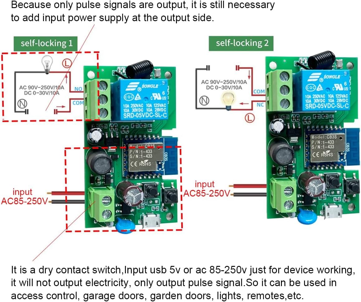
Figure 2: Wiring diagram for Self-Locking Mode. Connect the input power (AC 85-250V) to the module. The output (NO/COM) connects to the appliance, which requires its own power supply.
3.2 Inching Mode
In inching mode, the relay momentarily changes its state for a set duration (adjustable from 2 seconds to 1 hour in the app) and then returns to its original state. This is ideal for applications requiring a brief pulse, such as garage door openers or gate switches.
Two wiring options are available for inching mode:
- Turn on for X seconds and then auto-off.
- Turn off for X seconds and then auto-on.
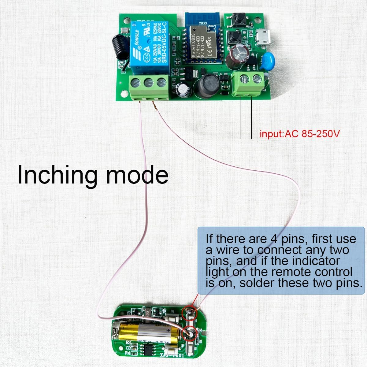
Figure 3: Wiring diagram for Inching Mode. This setup shows connecting the module to a remote control board. If the remote control has 4 pins, identify the correct two pins by testing with a wire until the indicator light illuminates, then solder those two pins.
3.3 Access Control Application
The inching mode is particularly useful for access control systems, such as connecting to a push switch for a gate or door.

Figure 4: Wiring diagram for Access Control (Inching Mode). The NO (Normally Open) and COM (Common) terminals are connected to the two ends of the access control push switch. The module receives its own 85-250V input power.
4. Smart Life/Tuya App Features
The Smart Life/Tuya app provides comprehensive control and automation capabilities for your Smart Switch:
- Remote Control: Turn connected devices ON/OFF from anywhere using your smartphone.
- Timing Schedules: Create countdown, count-up, single, or recurring schedules to automate device operation.
- Device Sharing: Share control of the Smart Switch with family members.
- Group Management: Organize multiple smart devices into groups for simultaneous control.
- Scene Linkage: Create smart scenes to trigger the Smart Switch based on various conditions (e.g., departure mode, home mode, temperature, humidity).

Figure 5: Mobile app interface for remote control, allowing users to turn devices on or off from any location.

Figure 6: Mobile app interface for setting timers and schedules, enabling regular automated operation of connected devices.
4.1 Voice Control
The Smart Switch is compatible with leading voice assistants, allowing for hands-free control:
- Amazon Alexa: Works with Amazon Echo, Echo Dot, Amazon Tap.
- Google Home: Works with Google Home, Google Nest.
- Apple Siri: Compatible via SmartThings integration.
4.2 Application Scenarios
The Smart Switch can be used in various home automation applications:
- Home lighting control
- Large chandelier control
- Gate switch automation
- Garage door opener control
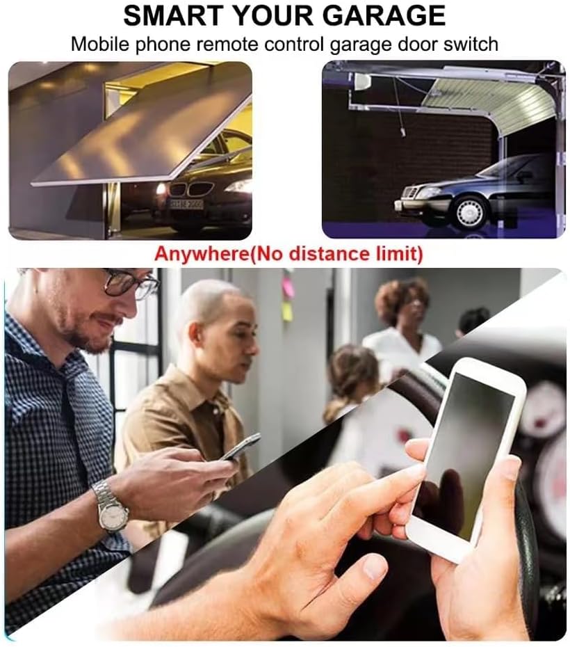
Figure 7: Example of using the Smart Switch for garage door automation, allowing remote control without distance limitations.

Figure 8: Visual examples of common application scenarios for the Smart Switch, including home lighting, chandeliers, gate control, and garage doors.
5. Maintenance
To ensure optimal performance and longevity of your Smart Switch, observe the following maintenance guidelines:
- Keep the device in a dry environment and avoid exposure to moisture or extreme temperatures.
- Clean the device periodically with a soft, dry cloth. Do not use harsh chemicals or abrasive cleaners.
- Ensure proper ventilation around the device to prevent overheating.
6. Troubleshooting
If you encounter issues with your Smart Switch, refer to the following common solutions:
- Device not pairing:
- Ensure your phone is connected to a 2.4GHz WiFi network. Temporarily disable 5GHz on your router if both bands share the same SSID.
- Make sure the Smart Switch is within close proximity to your WiFi router during pairing.
- If the indicator light does not flash slowly after holding the control key, try pressing and holding it again for more than 5 seconds.
- If pairing continues to fail, try configuring the device using the 'compatible mode' option in the app.
- No remote control:
- Check your WiFi connection and ensure the Smart Switch is online in the app.
- If WiFi is disconnected, the device may automatically switch to Bluetooth remote control (if supported and within range).
- Device unresponsive:
- Verify the power supply to the Smart Switch.
- Restart the device by disconnecting and reconnecting its power.
7. Specifications
| Feature | Specification |
|---|---|
| Model Number | TYWB1CH-B1 |
| Part Number | SHQY028 |
| Input Voltage | USB 5V or AC 85-250V |
| Max Current Rating | 10 Amps |
| Connectivity | 2.4GHz WiFi, Bluetooth, 433MHz RF (optional) |
| Operating Modes | Inching (Momentary), Self-Locking (Latching) |
| Contact Type | Normally Open (NO) |
| Product Dimensions | 2.87 x 1.82 x 1.14 inches |
| Item Weight | 1.42 ounces |
| Upper Temperature Rating | 70 Degrees Celsius |
| Material | Acrylonitrile Butadiene Styrene (ABS) |
| Manufacturer | Qianyi Technology.co.ltd |
8. Warranty and Support
For warranty information, please refer to the specific terms provided by the seller or manufacturer at the time of purchase. This document serves as an instruction manual and does not imply a warranty.
For technical support or further assistance, please contact the seller through your purchase platform or refer to the manufacturer's official support channels.